
 Home
Back
Home
Back
Author: Electron18
www.softelectro.ru
2009
electron18@softelectro.ru
RS-232 (Recommended Standard 232) - standard describes an interface for serial bi-directional data transfer between the terminal (DTE, Data Terminal Equipment) and end-device (DCE, Data Circuit-Terminating Equipment).
This legendary standard, which appeared in the 60's the 20 th century and became the basis for all subsequent serial interfaces for data exchange.
RS-232C interface has been applied in the first personal computers from IBM and to this day is a part of any PC in hardware or software form.
Decisions which are incorporated in this standard are used almost everywhere.
It is impossible to consider themselves industrial programmer did not know this standard
Interface RS-232 is fully hardware implemented on personal computers in the form of chips and connectors.
In the PC it is called the COM-port (Communication port).
Hardware implementation means that it always works, no matter which operating system is installed on the PC (it works without OS).
Programs can communicate with the COM ports all available means: a direct source microprocessor, hardware interrupts, functions, BIOS, operating system tools, components of high-level languages
COM port is implemented on standard RS-232-universal.
He made it work with PC peripherals (what is now busy with USB), the interaction with the local network via a modem (Ethernet), the exchange of data between the PC and industrial equipment (ModBus, etc.) to understand how these protocols need to understand what function the COM port they have undertaken.
Designation Standard:
RS-232(Recommended Standard 232).Recommended Standard 232.
Title:
Interface Between Data Terminal Equipment and Data Circuit-Terminating Equipment Employing Serial Binary Data Interchange.
Developers:
Electronics Industries Association (EIA). until 1997. Association of Industrial Electronics.
Electronics Industries Alliance (EIA).. after 1997. Alliance of industrial electronics industries.
Telecommunications Industry Association (TIA). joint EIA c 1988. Association of the telecommunications industry.
Revision of the standard:
RS-232A (Recommended Standard 232 Edition: A) 1962.
RS-232B (Recommended Standard 232 Edition: B) ????.
RS-232C (Recommended Standard 232 Edition: C) 1969.
EIA 232-D (RS-232D - not officially) 1986.
TIA/EIA 232-E (RS-232E - not officially) 1991.
TIA/EIA 232-F (RS-232F - not officially) 1997.
In the 60 years of last century began the rapid development of telecommunication technologies.
Numerous firms in the USA and other countries, producing communications equipment, used their own standards for data transmission.
Using this equipment does cause problems of their compatibility.
Connectors, electrical characteristics of signals, service alerts, synchronization mechanisms were different in different firms.
Some protocols coded symbols four bits, the other 5 bits, etc. to 8 bits.
The absence of an international standard for serial transmission of data hindered the development of the telecommunications industry.
In 1962, the Electronics Industries Association (EIA) has developed recommendations for equipment manufacturers, calling them "Recommended Standard 232.
RS-232 interface has been designed as universal as possible, allowing many producers can easily convert their equipment to this standard.
Encode characters allowed from 5 to 8 bits, the voltage signal could be from ± 3 to ± 25 V, etc.
It consists of 16 service signals, whose use was not mandatory.
Allowed to work, as in synchronous and asynchronous data transmission.
Such loyalty to the standard suit manufacturers of telecommunications equipment.
In 1969, the EIA released edition of the standard RS-232C, which has been accounted for seven-year experience of the standard RS-232A / B.
The final was legalized 25 pin DB25 and electrical characteristics of the signal ..
This edition has become the primary interface for serial data communication channels for many years to come.
International and national standards were to include part of the standard RS-232C in its structure.
In 1983, the company released the IBM PC IBM XT and IBM AT in 1984 with built-in universal transceiver UART.
UART designed for standard RS-232C, it supports data transmission only in asynchronous mode.
IBM XT supports up to 4 independent UART, which are called COM-ports (Communication port).
Originally connectors COM ports comply with standard RS-232C, ie a 25 pin connector DB25p.
Most of the service signals RS-232C in the UART is not used.
Therefore, a company IBM started using computers in their 9-pin connectors DE9p, which used six service signals of the standard RS-232C.
To legitimize the use of this connector TIA has released a new standard TIA-574.
Standard TIA-574 allowed to use the 9 pin connector in the telecommunications equipment operating on standard RS-232C.
With the development of international and national standards in the field of telecommunications, the role of EIA began to diminish.
In 1986, for maintaining the EIA for its image has replaced the name of standards with RS on EIA.
The role of the association has continued to decline and its duties transferred to the related Association TIA.
The Association TIA has released two version of the standard RS-232C with the name of TIA / EIA 232-E (1991) and TIA / EIA 232-F (1997).
Nothing new in the serial data, these standards are not brought, they are almost exactly like a standard RS-232C.
In 1997, the EIA Association ceased to exist, its successor has become an alliance of industrial electronics.
Today, EIA and TIA trade organizations.
Standards comprised of RS-232 standard large amount.
Below are some of these standards:
ITU-T v.24. (2000 acting)
Publisher: TELECOMMUNICATION STANDARDIZATION SECTOR OF ITU
Title: LIST OF DEFINITIONS FOR INTERCHANGE CIRCUITS BETWEEN DATA TERMINAL EQUIPMENT (DTE) AND DATA CIRCUIT-TERMINATING EQUIPMENT (DCE)
Oldest Received:
ITU-T v.24. (1996 not valid)
ITU-T v.24. (1993 not valid)
CCIT v.24. (1988 not valid)
ITU-T v.28 . (1993 acting)
Publisher: TELECOMMUNICATION STANDARDIZATION SECTOR OF ITU
Title:ELECTRICAL CHARACTERISTICS FOR UNBALANCED DOUBLE-CURRENT INTERCHANGE CIRCUITS.
Oldest Received:
CCIT v.28 (1988 not valid)
GOST 23675-79 (1979)
Publisher: USSR. State Committee on Standards.
Title:Chains joint C2 system of data transmission.
GOST 18145-81 (1981)
Publisher: USSR. State Committee on Standards.
Title:Chains at the junction of C2 equipment data with terminal equipment for serial input-output data.
GOST R 50668-94 (1994)
Publisher: National Standard RF
Title:Chains joint C2 system of data transmission.
ANSI/TIA/EIA-232-F (1997)
Publisher: USA. American National Standards Institute.
Title:Interface Between Data Terminal Equipment and Data Circuit-Terminating Equipment Employing Serial Binary Data Interchange.
This standart is applicable to the interconnection of data terminal equipment (DTE) and data circuit-terminating equipment (DCE) employing serial binary data interchange.
This standart includes thirteen specific interface configurations intended to meet the needs of fifteen defined system applications/ These configurations are identified by type, using alphabetic characters A through M. In addition, type Z has been reserved for applications not coverd by types A through M, and where the configuration of interchange circuits is to be specified, in each case, by the supplier.
This standart is applicable for use at data signaling rates up to a nominal limit of 20 kb/s.
This standart is applicable for the interchange of data, timing and control signals when used in conjunction with electronic equipment, each of which has a single common return, which can be interconnected at the interface point. It does not apply where electrical isolation between equipment on opposite sides of the interface point is required.
This standart applies to both synchronous and nonsynchronous serial binary data communication system.
Fig.1. shows the equivalent electrical circuit in the exchange of serial data standard RS-232
This equivalent circuit is independent of where the generator is located in the DTE or DCE.
The characteristics of the signal data exchange standard RS-232C are included in the international standard ITU-T v.28.

Junction between the RS-232C interface is the line connecting DTE cable plus DCE That is, the cable interface is part of the DTE.
Fig.2 Practical scheme of interface RS-232C interface
As a connector for RS-232C interface is selected miniature connector D-type (D-subminiature).
Terminal (DTE) - DB25p
For terminals (DCE) -DB25s
When using standard TIA / EIA 574 can be used 9-pin connectors:
For Terminal (DTE) - DE9p
For Endpoint (DCE) -DE9s
Now, these connectors are manufactured by many firms around the world and the specified label does not comply.
Often, instead DB25p (plug-"pin") indicate DB25m (male - "Dad"), DB25s (socket-"nest") - DB25f (femini-"Mama").
Also, instead of DE9p (COM-port) may indicate: DB9p, DB9m. (Although the clips "B" and "E" are different in size)
Fig.3. DB25 connector pinout for standard RS-232C
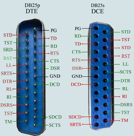
You can directly connect the device connectors DTE and DCE, as their signals are chosen appropriately. That is, the output signals DTE fall on the input signals DCE, and vice versa DCE output signals arrive at inputs DTE. Therefore, to connect the device with DTE DCE devices use a straight line (modem) cable. To connect DTE devices with each other or DCE devices together, use a crossover (crossover) cable.
In RS-232 interface is used:
16 service signals
4 information signal
2 common signal
The use of signals and do not necessarily depend on the application, where they are used.
For example, a minimum set of signals TD and GND, allows you to transfer data from the DTE to DCE standard RS-232c on the two wires.
International standard ITU-T v.24 includes a description of 37 signals, which are used to transfer binary data between a terminal (DTE) and the terminal connection (DCE).
All signals are RS-232C signals are included in the standard ITU-T v.24 under other names.
Corresponding signals of the standard RS-232C signals of standard ITU-T v.24 shown in the following table.
| Nr. | ITU v.24 | Name for RS232 | Defact | of DTE | Description |
| 1 | PG | Common | Protective Ground | ||
| 2 | 103 | BA | TD | Output | Transmited Data. The data signals originated by the DTE: 1)to be transmitted via a data channel to one or more remote data stations, 2)to be passed to the DCE for maintenance test purposes under control of the DTE, or 3)or the programming or control of serial automatic calling DCEs,are transferred on this circuit to the DCE. |
| 3 | 104 | BB | RD | Input | Received Data. The data signals generated by the DCE: 1)in response to data channel line signals received from a remote data station, 2)in response to the DTE maintenance test signals, or 3)in response to (or as an echo of) programming or control signals from the DTE where a serial automatic calling facility is implemented in the DCE, are transferred on this circuit to the DTE. Note – The reception conditions for maintenance test signals are specified with circuit 107. |
| 4 | 105 133 | CA/CJ | RTS | Output | Request To Send. Signals on this circuit control the data channel transmit function of the DCE. The ON condition causes the DCE to assume the data channel transmit mode. The OFF condition causes the DCE to assume the data channel non-transmit mode, when all data transferred on circuit 103 have been transmitted. |
| 5 | 106 | CB | CTS | Input | Clear To Send. Signals on this circuit indicate whether the DCE is prepared to accept data signals for transmission on the data channel or for maintenance test purposes under control of the DTE. The ON condition indicates that the DCE is prepared to accept data signals from the DTE. The OFF condition indicates that the DCE is not prepared to accept data signals from the DTE. |
| 6 | 107 | CC | DSR | Input | Data Set Ready. Signals on this circuit indicate whether the DCE is ready to operate. The ON condition, where circuit 142 is OFF or is not implemented, indicates that the signal converter or similar equipment is connected to the line and that the DCE is ready to exchange further control signals with the DTE to initiate transfer of data. The ON condition, in conjunction with the ON condition of circuit 142, indicates that the DCE is prepared to exchange data signals with the DTE for maintenance test purposes. The OFF condition, in conjunction with the ON condition on circuit 106, indicates that the DCE is ready to exchange data signals associated with the programming or control of serial automatic calling DCEs. The OFF condition, in conjunction with the OFF condition on circuit 106, indicates: 1) that the DCE is not ready to operate in the data transfer phase, 2) that the DCE has detected a fault condition (which may be network or DCE dependent) which has lasted longer than some fixed period of time, such period of time being network dependent, or 3) in switched network operation, that the DCE has detected a disconnect indication from the remote station or from the network. The OFF condition, in conjunction with the ON condition on circuit 142, indicates that the DCE is involved in tests from the network or remote station. |
| 7 | 102 | AB | GND | Common | Signal ground or common return This conductor establishes the signal common return for unbalanced interchange circuits with electrical characteristics according to Recommendation V.28 and the d.c. reference potential for interchange circuits according to Recommendations V.10, V.11 and V.35. |
| 8 | 109 | CF | DCD | Input | Data Carrier Detected. Signals on this circuit indicate whether the received data channel line signal is within appropriate limits, as specified in the relevant Recommendation for DCE. Circuit 109 may also be in the ON condition during the exchange of data signals between the DCE and the DTE, associated with the programming or control of serial automatic calling DCEs. The OFF condition indicates that the received signal is not within appropriate limits. |
| 9 | available | ||||
| 10 | available | ||||
| 11 | available | ||||
| 12 | 122 112 | SCF/CI | SDCD | Input | Secondary Carrier Detect. This circuit is equivalent to circuit 109, except that it is used to indicate whether the received backward channel line signal is within appropriate limits, as specified in the relevant Recommendation for DCE. |
| 13 | 121 | SCB | SCTS | Input | Secondary Clear To Send. This circuit is equivalent to circuit 106, except that it is used to indicate whether the DCE is conditioned to transmit data on the backward channel. The ON condition indicates that the DCE is conditioned to transmit data on the backward channel. The OFF condition indicates that the DCE is not conditioned to transmit data on the backward channel. |
| 14 | 118 | SBA | STD | Output | Secondary Transmitted Data. This circuit is equivalent to circuit 103, except that it is used to transmit data via the backward channel. |
| 15 | 114 | DB | TST | Input | Transmitter Signal Timing DCE source. Signals on this circuit provide the DTE with signal element timing information. The condition on this circuit shall be ON and OFF for nominally equal periods of time. The DTE shall present a data signal on circuit 103 in which the transitions between signal elements nominally occur at the time of the transitions from OFF to ON condition of circuit 114. |
| 16 | 119 | SBB | SRD | Input | Secondary Received Data. This circuit is equivalent to circuit 104, except that it is used for data received on the backward channel. |
| 17 | 115 | DD | RST | Input | Receiver Signal Timing. Signals on this circuit provide the DTE with signal element timing information. The condition of this circuit shall be ON and OFF for nominally equal periods of time, and a transition from ON to OFF condition shall nominally indicate the centre of each signal element on circuit 104. |
| 18 | 141 | LL | LL | Output | Local Loopback. Signals on this circuit are used to control the loop 3 test condition in the local DCE. The ON condition of circuit 141 causes the establishment of the loop 3 test condition in the local DCE. The OFF condition of circuit 141 causes the release of the loop 3 test condition in the local DCE. |
| 19 | 120 | SCA | SRTS | Output | Secondary Request to Send. This circuit is equivalent to circuit 105, except that it is used to control the backward channel transmit function of the DCE. The ON condition causes the DCE to assume the backward channel transmit mode. The OFF condition causes the DCE to assume the backward channel non-transmit mode, when all data transferred on circuit 118 have been transmitted to line. |
| 20 | 108/2 108/1 | CD | DTR | Output | Data Terminal Ready. Signals on this circuit control switching of the signal-converter or similar equipment to or from the line. The ON condition, indicating that the DTE is ready to operate, prepares the DCE to connect the signal-conversion or similar equipment to the line and maintains this connection after it has been established by supplementary means. The DTE is permitted to present the ON condition on circuit 108/2 whenever it is ready to transmit or receive data. The OFF condition causes the DCE to remove the signal-converter or similar equipment from the line, when the transmission to line of all data previously transferred on circuit 103 and/or circuit 118 has been completed. The OFF condition of this circuit may also be used to direct the DCE to abort or to clear a serial automatic calling operation (see Recommendation V.25 bis). |
| 21 | 140 110 | RL/CG | RL | Output | Remote Loopback. Signals on this circuit are used to initiate and release loopback or other maintenance test conditions in DCEs. The ON condition causes initiation of the maintenance test condition. The OFF condition causes release of the maintenance test condition. |
| 22 | 125 135 | CE/CK | RI | Input | Ring Indicator. Signals on this circuit indicate whether a calling signal is being received by the DCE. The ON condition indicates that a calling signal is being received. The OFF condition indicates that no calling signal is being received, and this condition may also appear during interruptions of a pulse-modulated calling signal. |
| 23 | 111 112 | CH/CI | DSRS | Output | Data Signal Rate Selector. Signals on this circuit are used to select one of the two data signalling rates of a dual rate synchronous DCE, or to select one of the two ranges of data signalling rates of a dual range asynchronous DCE. The ON condition selects the higher rate or range of rates. The OFF condition selects the lower rate or range of rates. |
| 24 | 113 | DA | TST | Output | Transmitter Signal Timing DTE source. Signals on this circuit provide the DCE with signal element timing information. The condition on this circuit shall be ON and OFF for nominally equal periods of time and the transition from ON to OFF condition shall nominally indicate the centre of each signal element on circuit 103. |
| 25 | 142 | TM | TM | Input | Test Mode. Signals on this circuit indicate whether a maintenance condition exists. The ON condition indicates that a maintenance condition exists in the DCE, precluding reception or transmission of data signals from or to a remote DTE. The OFF condition indicates that the DCE is not in a maintenance test condition. |
Since the RS-232C interface is universal, it means the use in different applications and conditions. For each application can use different combinations of interface signals, which are called configurations. Standard RS-232C provides 13 standard configurations, A-M and one custom configuration Z.
The work of communication ports implemented on the universal asynchronous receiver / transmitter UART.
UART-IC is that work on standard RS-232C D configuration with the option of switching services (2.5.5)
For the COM port of your computer using a 25-pin connector DB25p according to the standard RS-232C or 9-pin connector DE9p according to standard TIA-574.
This connector uses six service signals and one duplex communication channel.
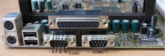
Fig.4 Type connectors COM1 and COM2 on the motherboard.
UART uses signal levels ....+ 12V-12V. Dead zone, ie the absence of signals is the voltage-3V to +3 .... However, note that the adopted / transmitted data is inverted
Fig.6. Levels of signals UART standard RS-232c
When transferring data symbols are transmitted from the transmitter buffer sequentially (first-come-first-out). Specially called characters, not bytes as characters may have a size of 5 to 8 bits. Each transmitted symbol is provided with start and stop bits, designed to synchronize at the receiving side. After the start bit followed by data bits, starting with low bit and ending with the seniors. For the last bit of data symbol may be followed by a bit of parity to detect transmission errors of data bits. The last stop bit is transmitted, which is required for the temporary separation of transmitted symbols
Fig.7 is shown the transfer of characters "0" "0" no parity, one stop bit
Figure 7 clearly seen that the stop bit separates the two transmitted symbol. You can increase this interval to 2 stop bits, if the endpoint is unable to separate symbols.
Fig.8 is shown the transfer of characters "0" "0" with parity (EVEN), with one stop bit
Null-modem connection between two COM ports.
In this connection, computers (terminals) connected to each other directly via COM ports without the use of modems. As computers have high-speed data processing, then synchronize their work is not necessary. It is therefore assumed that the synchronization mode exchange (Handshaking): 0-None, that is, service signals do not affect the data exchange procedures. To do this, use a null-modem cable.
Fig.9 null-modem cable for Handshaking = 0 (None)
Since the synchronization mode of exchange at the COM ports can be switched on, the service often signals the COM ports enclose themselves to themselves, thereby eliminating their influence on the exchange procedure.
Fig.10 null-modem cable for all modes Handshaking
If you can use a full cable, but the COM ports must be configured with a hardware synchronization exchange.
Fig. 11 null-modem cable for hardware synchronization mode Handshaking = 2
Modem connection.
Modem connection means connect the two computers (DTE) via modems (DCE). Modems (modulator-demodulator) - a special device to allow exchange of data on almost unlimited range, using the modulation and demodulation of information signals. Therefore, dial-up connection means to connect the COM port on your computer (DTE) to the end device (DCE). Usually in such a connection using a hardware synchronization Handshaking = 2. This mode allows the modem to manage the process of data.
Fig. 12 A typical modem cable.
Hardware synchronization of data exchange RTS / CTS (hardware flow control) Handshaking = 2, uses the service signals to RS-232C to control the flow of data.
Fig.13. Sharing with the hardware synchronization.
As shown in Figure 13 uses a modem signal CTS, which allows you to stop the transmission of data, if the receiver is not ready to receive them. The transmitter "released" the next byte only when the line CTS. Bight, which had already begun to spread, delay signal CTS is impossible (this ensures the integrity of the parcel). The hardware protocol provides the fastest response of the transmitter on the state of the receiver.
The software protocol for flow control XON / XOFF (Handshaking = 1). Protocol works as follows: if the device receiving the data reveals the reasons why it can not continue to take it on the reverse channel sends a byte-symbol XOFF (13hex). The opposite device, by adopting this symbol, suspend the transfer. When the receiving device is again ready to receive data, it sends a XON (11hex), which is taking the opposite device resumes the transfer. The response time of the transmitter to change the status of the receiver compared to a hardware protocol increases, at least at the time of transmission character (XON or XOFF), plus the response time of the program the transmitter to the reception symbol. The advantage of software protocol is not necessary to transfer control signals interface - minimal cable for two-way exchange can only have 3 wires. The disadvantage of this method is more time to respond and exclusion from the transmitted flux of the two characters (13hex, 11hex).
There is a mixed method for synchronizing data exchange RTS / XOn / Xoff (Handshaking = 3), which is an amalgamation of two previous methods.
To encode characters transmitted via RS-232C uses a table of encoding used symbols and control characters.
Fig.14 The standard ASCII code table
The first 32 characters of code page are the control characters that are designed to control the modem. For example, the use of symbols 17 (11hex) and 19 (13hex) described above, in a software method of controlling the exchange. These characters were developed mainly to manage printers and modems
| 00(00hex) - NUL empty symbol | 08(08hex)- BS backspace | 16(10hex)- DLE code switching | 24(18hex)- CAN cancel |
| 01(01hex)- SOH start of header | 09(09hex)- HT horizontal tab | 17(11hex)- DC1 control the first device (XON) | 25(19hex)- EM end of medium |
| 02(02hex)- STX start of text | 10(0Ahex)- LF line feed | 18(12hex)- DC2 control the second device | 26(1Ahex)- SUB substitution |
| 03(03hex)- ETX end of text | 11(0Bhex)- VT vertical tabulation | 19(13hex)- DC3 control device to third (XOFF) | 27(1Bhex)- ESC escape |
| 04(04hex)- EOT end of transmission | 12(0Chex)- FF Form feed (new page) | 20(14hex)- DC4 fourth control device | 28(1Chex)- FS file separator |
| 05(05hex)- ENQ request | 13(0Dhex)- CR carriage return | 21(15hex)- NAK originator referral | 29(1Dhex)- GS group separator |
| 06(06hex)- ACK confirmation | 14(0Ehex)- SO transition to upper case | 22(16hex)- SYN synchronous standby | 30(1Ehex)- RS record separator |
| 07(07hex)- BEL bell | 15(0Fhex)- SI transition to lower case | 23(17hex)- ETB end of transmission block | 31(1Fhex)- US unit separator |
For the hardware implementation of the COM ports for RS-232 standard uses a specialized chip UART. UART (Universal Asynchronous Receiver-Transmitter) - universal asynchronous receiver-transmitter. I8250 chip installed in the IBM XT marked the beginning of a series of chip UART, which were installed on the motherboard PC.
ICs manufactured by various companies producing: Intel, National Semiconductor, Maxim, etc.
This chip is controlled by a logic circuit with a buffer register for receiving and transmitting serial data.
Buffer registers allow to transmit and receive data without CPU.
Accordingly, the greater the capacity of the buffer register, the less chip interrupts CPU.
Buffer registers are arranged on a "queue" (FIFO) - first come, first-served.
Having a portion of data in the transmitting buffer register, UART begins transmitting it to the network RS-232, while it can receive data from the network RS-232 to the reception buffer register.
Software at any time may apply to the receive buffer UART, thus freeing him to receive the following data.
When filling out the receive buffer UART can interrupt CPU, informing him of the buffer is full.
Filling in the receive buffer will stop receiving data from the network RS-232, until it will not be read.
Consider the example of the work UART chip PC16550D
Fig.15 Standard scheme include UART PC16550D with microprocessor Intel 8088
Appeal to the chip via the address space I / O ports CPU.
Circuit is connected to the system bus when activated signal CS0, which is produced when handling CPU to the specified range of addresses of the port.
Address I / O ports are set in the BIOS. Usually they have the values: COM1 = 3F8h, COM2 = 2F8h, COM3 = 3E8h, COM4 = 2E8h.
The inputs UART A0, A1, A2 served three junior level address bus CPU.
Address specified in the BIOS is the start address of address range (A2A1A0 = 000).
Hence a full range of addresses for each port is 8 addresses (from A2A1A0 = 000 A2A1A0 = 111).
For example, COM4, 2E8h, 2E9h, 2EAh, 2EBh, 2ECh, 2EDh, 2EEh, 2EFh.
The distance between the starting port address is 16, which allows further use of chips with four initial address lines.
Appeal to the chip at a particular address provides access to the group of control registers or buffer registers to send and receive.
CPU can write data to the UART registers putting signal WR = 0, or read the data, putting the signal RD = 0.
UART has 12 registers that can be accessed on the eight input-output port address.
Since the individual addresses for each register is missing, then use the splitting of the address space using the following methods:
1.Separation of one address space into two register write / read.
When the signal is read RD = 0 read one register, on a signal recording WR = 0 is written the second register.
That is, data on the same address written to or read from different registers
There are four registers:
THR, RBR - at UART 00h(A2A1A0=000)
IIR, FOR - at UART 02h(A2A1A0=010)
These registers are unilateral, that is, one can only record, in others only read the data.
2.The use of additional address bits
Use the 7th bit register LCR-located at UART 03h (A2A1A0 = 011).
This bit is called the DLAB, when DLAB = 0, then the read / write using one register
If DLAB = 1, then the read / write using the second register.
Such registers are five:
THR & RBR), DLL - at UART 00h (A2A1A0 = 000)
DIM, IER - at UART 01h (A2A1A0 = 001)
| address | DLAB | Read/Write | Register Name |
| 00h | 0 | WR | THR(Transmit Holding Register) |
| 00h | 0 | RD | RBR(Receiver Buffer Register) |
| 00h | 1 | RD/WR | DLL(Divisor Latch LSB) |
| 01h | 1 | RD/WR | DIM(Divisor Latch MSB) |
| 01h | 0 | RD/WR | IER(Interrupt Enable Register) |
| 02h | х | RD | IIR(Interrupt Identification Register) |
| 02h | х | WR | FCR(FIFO Control Register) |
| 03h | x | RD/WR | LCR(Line Control Register) |
| 04h | x | RD/WR | MCR(Modem Control Register) |
| 05h | x | RD/WR | LSR(Line Status Register) |
| 06h | x | RD/WR | MSR(Modem Status Register) |
| 07h | x | RD/WR | SCR(Scratch Pad Register) |
Figure 14 Functional diagram of UART PC16550.
THR-Transmit Holding Register (write-only)
(Transmit Holding Register)
In this register write data bytes, defined as a character (from 5 to 8 bits) which will be referred to a communication line.
Symbol, adopted at THR is transmitted further in the shift register bit junior forward (see Figure 7).
At the beginning of a symbol is added to start bit, the end of the symbol is added to stop bit.
Before the stop bit may be a bit of parity.
If the symbol is shorter than 8 bits, then the older bits in the register THR ignored (not used, although written in this register).
Register THR may take only one byte of data and transmit it to the serial shift register.
Most UART mode is FIFO, where data is loaded not in THR, but the register FIFO.
For example, UART PC16550 a register FIFO, which can take 16 bytes of data.
In addition, there are some UART mode DMA, in this mode, the shift register is filled with bytes of data directly from memory without the microprocessor.
To indicate that the THR register is empty and it can be downloaded the next byte of data using bit 5 of register LSR.
This bit is called the THRE (Transmitter Holding Register Empty) - "awaiting transfer data register is empty."
If the THRE = 1, then the register THR can send another data byte in the FIFO mode, this bit indicates that the register FIFO is empty and you can send the next packet of data bytes.
Beat THRE interrupt may be the source CPU.
RBR- receiver buffer register (read only)
(Receiver Buffer Register)
In this case bytes (characters) are taken from the receive shift register.
Register of RBR can take only one byte of shearing the receiver register.
Similarly, the transmission of UART there is a register FIFO, which can take longer than one byte of data passing register RBR.
By the time of completion of a shift register receiving register RBR must be released to receive the next byte, otherwise there will be overflow error.
When RBR register occurs when data is read from the microprocessor.
That character is lost as a result of the overflow register bit 1 reports LSR.
This bit is called the OE (Overrun Error) - "overflow error", OE = 1 means that one of the transmitted symbols is lost.
That byte is ready for reading by a microprocessor (ie fully detrained from the output shift register or FIFO) said bit 0 register LSR.
This bit called DR (Receiver Data Ready) - "These receivers are ready."
DR = 1 indicates that the register RBR (or FIFO) has received bytes and must be read, DR is reset to zero after reading the register RBR microprocessor.
This bit may also initiate interrupt the microprocessor.
DLL-low byte of the frequency divider: 16 (read / write)
(Divisor Latch LSB)
In this register is the low byte of the frequency divider divided by 16.
DIM-hig byte on the frequency divider: 16 (read / write)
(Divisor Latch MSB)
In this case is the highest byte of the frequency divider divided by 16.
In the chip UART frequency quartz master is divided by frequency divider (Decimal Divisor), which is obtained from the two-byte number (DIM, DLL) multiplied by 16.
Thus the frequency divider sets the speed of data exchange via UART.
Entry registration DIM and DLL senior and junior two-byte number of bytes that you specify the exchange rate of the COM port in bits / sec
For quartz UART frequency f = 1,8432 MHz frequency divider: 16 is the formula
D=115200/V, where V-speed in bit / sec, D = frequency divider: 16
For quartz UART frequency f = 24 MHz, the frequency divider: 16 is the formulaD=1 500 000/V, where V-speed in bit / sec, D = frequency divider: 16
| 1,8432 МГц | 24 МГц | |||||
|---|---|---|---|---|---|---|
| Speed bps | subgroup: 16 | DIM | DLL | subgroup: 16 | DIM | DLL |
| 50 | 2304 | 09h | 00h | 30000 | 75h | 30h |
| 75 | 1536 | 06h | 00h | 20000 | 4Eh | 20h |
| 110 | 1047 | 41h | 07h | 13636 | 35h | 44h |
| 150 | 768 | 03h | 00h | 10000 | 27h | 10h |
| 300 | 384 | 01h | 80h | 5000 | 13h | 88h |
| 600 | 192 | 00h | C0h | 2500 | 09h | C4h |
| 1 200 | 96 | 00h | 60h | 1250 | 04h | E2h |
| 1 800 | 64 | 00h | 40h | 833 | 03h | 41h |
| 2 000 | 58 | 00h | 3Ah | 750 | 02h | EEh |
| 2 400 | 48 | 00h | 30h | 625 | 02h | 71h |
| 3 600 | 32 | 00h | 20h | 417 | 0h | A1h |
| 4 800 | 24 | 00h | 18h | 312 | 01h | 38h |
| 7 200 | 16 | 00h | 10h | 208 | 00h | D0h |
| 9 600 | 12 | 00h | 0Ch | 156 | 00h | 9Ch |
| 14 400 | 8 | 00h | 08h | 104 | 00h | 68h |
| 19 200 | 6 | 00h | 06h | 78 | 00h | 4Eh |
| 28 800 | 4 | 00h | 04h | 52 | 00h | 34h |
| 38 400 | 3 | 00h | 03h | 39 | 00h | 27h |
| 57 600 | 2 | 00h | 02h | 26 | 00h | 1Ah |
| 115 200 | 1 | 00h | 01h | 13 | 00h | 0Dh |
| 250 000 | x | x | x | 6 | 00h | 06h |
| 300 000 | x | x | x | 5 | 00h | 05h |
| 375 000 | x | x | x | 4 | 00h | 04h |
| 500 000 | x | x | x | 3 | 00h | 03h |
| 750 000 | x | x | x | 2 | 00h | 02h |
| 1 500 000 | x | x | x | 1 | 00h | 01h |
IER-interrupt enable register (read / write)
(Interrupt Enable Register)
Interrupt enable register allows the resolution of certain events causing interruption of the microprocessor.
Bit 0. RxD_IE If RxD_IE = 1, then allowed to interrupt for receiving data, this interrupt occurs when it is necessary to take a symbol from the register of RBR (in regime FIFO - interrupt timeout).
Bit 1. TxD_IE - If TxD_IEE = 1, then allowed to interrupt for data transmission, this interrupt occurs when the transmitting buffer is empty and need to download the bytes in the register of THR.
Bit 2. RxL_IE - If RxL_IE = 1, then allowed to interrupt at breakage of communication lines or an error in receiving data, this interrupt occurs when the line status register LSR connection will be exposed bits of these errors.
Bit 3. Mod_IE - If Mod_IE = 1, then allowed to interrupt when changing the status of any of the input signals RST, CTS, DCD, RI, this interrupt occurs when the state of the input signals COM-port has changed.
Bit 4..7. Not used, always equal to 0.
IIR-register identifies the interrupting (Read)
(Interrupt Identification Register)
To minimize software, UART has prioritized interrupts into four levels and records these interruptions in the IIR.
Four levels of interrupt are arranged in order of priority conditions for termination specified register - RLS; RDR; THR; and MSR.
When the CPU accesses IIR, UART freezes all interrupts and indicates the highest priority deferred interrupt for the CPU.
During interrupt processing, UART records new interrupts, but does not alter their current sign, to complete processing.
Bit 0. IP(Interrupt Pending) If IP = 1, then all interrupts are processed. If IP = 0, ie the raw interrupts.
Bit 1. I_ID0(Interrupt ID Bit0) Zero bit interrupt identifier
Bit 2. I_ID1(Interrupt ID Bit1)- First bit of the interrupt identifier
Bit 3. I_ID2(Interrupt ID Bit2)- The second bit interrupt identifier
| I_ID2 | I_ID1 | I_ID0 | Priority | Identification |
| x | 0 | 0 | Fourth | Changed the modem status, reset the register reading MSR. |
| x | 0 | 1 | Third | Register THR launch, expected bytes of CPU. Reset write byte in THR |
| x | 1 | 0 | Second | Received data bytes in the register of RBR, resets the register reading RBR. |
| x | 1 | 1 | Highest | Break the line or error on the line, reset the register reading LSR. |
| I_ID2 | I_ID1 | I_ID0 | Priority | Identification |
| 0 | 0 | 0 | Fourth | Changed the modem status, reset the register reading MSR. |
| 0 | 0 | 1 | Third | The buffer register transfer FIFO trigger, waiting for data from the CPU. Reset the record in the transmitting FIFO buffer |
| 0 | 1 | 0 | Second | Receiving FIFO buffer is full, reset reading the receive buffer FIFO. |
| 0 | 1 | 1 | Highest | Break lines or error on the line, dropped reading LSR register |
| 1 | 0 | 0 | ||
| 1 | 0 | 1 | ||
| 1 | 1 | 0 | Second | LED timeout (per 4-fold interval symbol is not transmitted and not taken a single character, although in buffer FIFO has at least one character). Reset is performed reading the receive buffer FIFO. |
| 1 | 1 | 1 |
| FE_ID1 | FE_ID0 | Mode |
| 0 | 0 | Normal mode, data is transferred byte by byte through the registers and THR RBR |
| 0 | 1 | |
| 1 | 0 | mode FIFO for UART 16550. |
| 1 | 1 | mode FIFO for UART 16550A. |
FCR-register mode control FIFO (record)
(FIFO Control Register)
This register is used only for recording, the data are located in the register IIR.
This register is used to resolve regimes FIFO, clear the buffers FIFO, set the level of filling buffers FIFO, and select the type of DMA (direct memory access).
Bit 0. TRFIFOE(Transmit And Receive FIFO Enable)- Record 1 to this bit allows both FIFO mode transmitter (XMIT) and receiver (RCVR).
Reset bit to 0 will clear all bytes in both buffers FIFO.
When FIFO mode is changed to 16450 and vice versa, FIFO buffers are automatically cleared.
This bit must be 1, when the recording of your other bits of the register FCR, otherwise they will not be programmed.
Bit 1. RESETRF(Reset Receiver FIFO)-Record 1 to this bit clears all bytes in the receive buffer FIFO and resets its counter to 0.
Shift register is not cleared at the same time.
Thereafter 1 in this bit is reset to 0.
Bit 2. RESETTF(Reset Transmitter FIFO)- Record 1 to this bit clears all bytes in the transmitter buffer FIFO and resets its counter to 0.
Shift register is not cleared at the same time.
Thereafter 1 in this bit reset to 0.
Bit 3. DMAE(DMA Enabled)- Record 1 in this bit changes the signal UART RxRDY and TxRDY from 0 to 1, provided that the FCR (bit0) = 1.
These hardware signals are used to organize work properly for DMA in the microprocessor system.
Bit 4..5.Reserved.
Bit 6. ITL_ID0 (Interrupt Trigger Level ID bit0) - Zero bit identifier trigger level interrupts.
Bit 7. ITL_ID1(Interrupt Trigger Level ID bit1)- First bit of the ID trigger level interrupt.
These two bits set identifier, which specifies the level at which the interrupt will be generated when receiving data in a mode FIFO. Level sets the number of bytes in the receiver (RCVR) buffer FIFO.
| ITL_ID1 | ITL_ID0 | level interrupt byte |
| 0 | 0 | 01 |
| 0 | 1 | 04 |
| 1 | 0 | 08 |
| 1 | 1 | 14 |
LCR-line control register communication (read / write)
(Line Control Register)

This register is used to determine (set) the format of the exchange of asynchronous data transfer
Also in this mode, set bit DLAB, which allows the programmer to write and read data from the desired registers ..
The programmer can not only write but also read the contents of register LCR.
The ability to read simplifies system programming and eliminates the need for a separate area in system memory for storing the characteristics of the line.
Bit 0. SDB_ID0(Serial Data Bits ID0) Zero bit ID number of bits in the transmitted symbol.
Bit 1. SDB_ID1(Serial Data Bits ID1)- First bit of the ID number of bits in the transmitted symbol.
With these bits specify the number of bits to send or receive symbol.
| SDB_ID1 | SDB_ID0 | the number of bits in a symbol |
| 0 | 0 | 5 |
| 0 | 1 | 6 |
| 1 | 0 | 7 |
| 1 | 1 | 8 |
MCR-modem control register (read / write)
(Modem Control Register)
This register controls the interface modem or peripheral device.
Bit 0. DTR(Serial Data Bits ID0)(Data Terminal Ready)- This bit controls the output signal DTR (data terminal ready).
When the bits DTR = 1, DTR UART output is set to logic 0, the IBM XT, this signal is inverted by inverter buffer DS1488 (sm.ris.15) to logic 1 ie U = +12 in the (signal DTR COM-port is included)
Accordingly, when the bits DTR = 0, the signal DTR COM-port U =-12V logic 0 (DTR signal is off)
Bit 1. RTS(Request To Send )- This bit controls the output signal of RTS (Request to send).
When a bit RTS = 1, RTS UART output is set to logic 0, the IBM XT, this signal is inverted by inverter buffer DS1488 (sm.ris.15) to logic 1 ie U = +12 in the (signal RTS COM-port is included)
Accordingly, when a bit of RTS = 0, the signal RTS COM-port U =-12V logic 0 (RTS signal is turned off)
Bit 2. OUT1(OUT1 Bit Control) - Control of auxiliary output OUT1.
Bit 3. OUT2(OUT2 Bit Control) - Control of auxiliary output OUT2.
Bit 4. LOOP(Loopback Mode Enable) Bit mode diagnosis. When LOOP = 0, then the UART operates normally. When LOOP = 1, then URAT member of the stuff diagnostic mode with feedback, in this mode auxiliary signals OUT1 and OUT2.
Bit 5..7. Reserved.
LSR-line status register communication (read / write)
(Line Status Register)
This register shows the state of the transceiver.
Bit 0. DR(Receiver Data Ready) — Availability of data priemnika.DR = 1 informs that the data received and loaded into the RBR register or receive buffer FIFO.
Bit is reset to zero when all data will be read from the CPU register or buffer RBR FIFO.
Bit 1. OE(Overrun Error) — bits overflow. Bit indicates that the data in the register of RBR were not read by CPU before the next character was transferred to the RBR, which led to the loss of the previous character.
Bit set to OE = 1, after the detection of overflow and reset whenever the SPU reads the contents of the register LSR.
Bit 2. PE(Parity Error) Bit-error control bits pariteta.PE = 1 if the character is received with parity error.
Bit 3. FE(Framing Error) Frame error (wrong stopbit).
Bit 4. BD(Break Detected)- Indicator line break (the receiver input is at 0 least now make a character).
Bit 5. THRE(Transmitter Holding Register Empty) - Register the transmitter is ready to accept bytes for transmission. In the FIFO mode, indicating a lack of characters in the FIFO-buffer transfer. It may be the source of interruption.
Bit 6. TEMPT(Transmitter Empty Status) Register the transmitter is empty (no data for transmission or in the shift register, or in the buffer THR or FIFO).
Bit 7. FIFOE(FIFO Error Status) Error is made on-line data FIFO (buffer contains at least one symbol, adopted by the error size, parity or a cliff). In no FIFO-mode is always 0.
MSR-modem status register
(Modem Status Register)
This register allows the CPU to control the current state of control lines modem or peripheral device.
In addition, four bits (0 .. 3) MSR register control signal change at the inputs of CTS, RTS, RI, DCD chips and generate interrupt the microprocessor.
Bit 0. DCTS(Delta Clear To Send) - Change state signal CTS (cleared to send). Bit is set to DCTS = 1 when changing the CTS signal at the input circuit and is reset when reading the MSR register of the microprocessor.
When you install the bits in a generated interrupt the microprocessor.
Bit 1. DDSRDelta Data Set Ready) - Changing the status signal DSR (setting data is ready). Bit is set in DDSR = 1 when changing the DSR signal input circuit and is reset when reading the MSR register of the microprocessor.
When installing a bit in a microprocessor interrupt is generated.
Bit 2. ТERI(Trailing Edge Of Ring Indicator) - Detect the trailing edge signal RI (ring indicator). Bit set to TERI = 1, when the signal on pins RI changes its level from low to high. Bit is reset to TERI = 0 when reading MSR register microprocessor.
When installing a bit in a microprocessor interrupt is generated.
Bit 3. DDCD(Delta Data Carrier Detect) - Changing the status signal DCD (detected information carrier). Bit is set in DDCD = 1 when changing the DCD signal on the input circuit and is reset when reading the MSR register of the microprocessor.
When installing a bit in a microprocessor interrupt is generated ..
Bit 4. CTS(Clear To Send) - Line Status CTS. If CTS = 1, then the input of the CTS COM port voltage is +12 V (CTS signal is active). If CTS = 0, then the input COM port voltage is-12V (CTS signal is passive).
In the diagnostic mode this bit is equivalent to the RTS bit register MCR.
Bit 5. DSRData Set Ready) - Line Status DSR. If DSR = 1, then the input of the DSR COM port voltage is +12 V (DSR signal is active). If DSR = 0, then the input COM port voltage is-12V (DSR signal is passive).
In the diagnostic mode this bit is equivalent to the DTR bit register MCR.
Bit 6. RI(Ring Indicator) - Status line RI. If RI = 1, then the input of the DSR COM port voltage is +12 V (RI signal is active). If RI = 0, then the input COM port voltage is-12V (RI signal is passive).
In the diagnostic mode this bit is equivalent to OUT1 bit register MCR.
Bit 7. DCD(Data Carrier Detect) - Line Status DCD. If DCD = 1, then the input DCD COM port voltage is +12 V (DCD signal is active). If DCD = 0, then the input COM port voltage is-12V (DCD signal is passive).
In the diagnostic mode this bit is equivalent to OUT2 bit register MCR.
(SCR-register for temporary storage (read / write)
(Scratch Pad Register)
Register for temporary storage, work does not affect UART is designed for temporary storage of data (UART i8250 absent).
UART mode diagnosis enables you to test COM ports are not connected to them peripherals.
Diagnostic mode enabled bit LOOP = 1 register MCR.
It is organized within the UART hardware "flags":
In MS-DOS programming COM ports can be the whole range of software tools: the direct source microprocessor (assembler), features BIOS, operating system, high level programming language.
Under the direct programming code refers to programming the microprocessor UART chip through I / O ports with the commands of the microprocessor.
The system commands the microprocessor commands the OUT and IN, which allow to read / write bytes to the address I / O port.
In p.3.12 described 12 registers chip UART, which completely determine the specified chip.
You simply write the necessary data to these registers to make the COM port to perform the desired action.
When programming the UART registers to keep in mind that the memory addresses are BIOS I / O ports for COM 1 ... COM4.
By default, they equal COM1 = 3F8h, COM2 = 2F8h, COM3 = 3E8h, COM4 = 2E8h, but there are "Crank" that can change them in the settings of BIOS.
Therefore, before the programming port to MS-DOS it is desirable to check the addresses of the COM ports.
The BIOS address of COM port occupies 2 bytes, and are in the memory cells at addresses COM1: 40 ... 41h, COM2: 42 ... 43h, SOM3: 44 ... 45h, COM4: 46 ... 47h.
'write the LCR mode COM port:
'8 bits per symbol, 1 stop bit, parity check on the parity issue in the case of termination 0, DLAB = 1
	mov al,DBh 'writes in the AL value for the register LCR = DBh
	mov dx,3fbh
	out dx,al'writes data to the register UART LCR
'set the exchange rate 115 000 bps DIM = 00h, DLL = 01h
	mov al,01h
        mov dx,3f8h
	out dx,al 'write register DLL = 01h
	mov al,00h
        mov dx,3f9h
	out dx,al 'write register DIM=00h
'charge a bit DLAB = 1
	mov al,5Bh 'DLAB=0
        mov dx,3fbh
	out dx,al
'send byte 03h in the line of communication
	mov al,03h
        mov dx,3f8h
	out dx,al 'sends a byte of 03h at a speed of 115,000 bits / sec
Before recording bytes of data in the register of the transmitter must ensure that the register storing the transmitter is free, that is to make sure that the transfer of the previous character is complete.
Indication that the transmitter register is free, is set bit 5 (THRE = 1) line status register LSR
In the same way as is done in the transfer of data before entering a character from the port receiver must make sure that bit 0 of LSR register is set (ie, DR = 1).
This means that the symbol adopted from the line and is located in the buffer unit.
The BIOS has functions that can be performed by a team of software interrupts microprocessor INT 00h ... INT 1Fh.
Since the code of these functions is located in the BIOS, then their implementation is possible even when no operating system on your PC.
In addition, the BIOS functions operate on the numbers of COM ports, but not at I / O, significantly more convenient.
The function of interrupt INT 14h
	mov ah,00h 'number function
	int 14h    'function call
Consider the function caused by INT 14h:
| inputs INT14h AH=00h | ||
| Register | Hig | low |
| AX | 00h | byte communication parameters |
| BX | ||
| CX | ||
| DX | (n-1), Where n-number of COM port | |
| byte communication parameters | |||||||||
| 7 | 6 | 5 | 4 | 3 | 2 | 1 | 0 | description | allowable values |
| x | x | x | speed bps | 000- 110 001- 150 010- 300 011- 600 100- 1200 101- 2400 110- 4800 111- 9600 | |||||
| x | x | parity | 00- no 01- odd 10- no 11- even | ||||||
| x | length of stop bit | 0- 1 1- 2 | |||||||
| x | x | count. bits per symbol | 10- 7 11- 8 | ||||||
	mov ah,00h 'number function
	mov al,EBh '9600 bps,odd,1 stop, 8 bit
	int 14h    'function call
After the function returns the output parameters:
| output parameters INT14h AH=00h | ||
| register | Hig | Low |
| AX | byte state line LSR | byte of the modem status MSR |
| BX | ||
| CX | ||
| DX | ||
| inputs INT14h AH=01h | ||
| register | Hig | Low |
| AX | 01h | character |
| BX | ||
| CX | ||
| DX | (n-1), where n-number of COM port | |
| output parameters INT14h AH=01h | ||
| register | Hig | Low |
| AX | byte state line LSR | character |
| BX | ||
| CX | ||
| DX | ||
| inputs INT14h AH=02h | ||
| register | Hig | Low |
| AX | 02h | |
| BX | ||
| CX | ||
| DX | (n-1), where n-number of COM port | |
| output parameters INT14h AH=02h | ||
| register | Hig | Low |
| AX | byte state line LSR | character |
| BX | ||
| CX | ||
| DX | ||
| output parametersINT14h AH=03h | ||
| register | Hig | Low |
| AX | 03h | |
| BX | ||
| CX | ||
| DX | (n-1), where n-number of COM port | |
| output parameters INT14h AH=03h | ||
| register | Hig | Low |
| AX | byte state line LSR | byte of the modem status MSR |
| BX | ||
| CX | ||
| DX | ||
| inputs INT14h AH=04h | ||
| register | Hig | Low |
| AX | 04h | setting interrupt |
| BX | Set Parity | setting of stop bit |
| CX | bits per character | speed, bps |
| DX | (n-1), where n-number of COM port | |
| output parameters INT14h AH=04h | ||
| register | Hig | Low |
| AX | byte state line LSR | byte of the modem status MSR |
| BX | ||
| CX | ||
| DX | ||
| output parameters INT14h AH=05h | ||
| register | Hig | Low |
| AX | 05h | 00h |
| BX | ||
| CX | ||
| DX | (n-1), where n-number of COM port | |
| output parameters INT14h AH=05h | ||
| register | Hig | Low |
| AX | ||
| BX | Register MCR | |
| CX | ||
| DX | ||
| output parameters INT14h AH=05h | ||
| register | Hig | Low |
| AX | 05h | 01h |
| BX | Register MCR | |
| CX | ||
| DX | (n-1), where n-number of COM port | |
| output parameters INT14h AH=05h | ||
| register | Hig | Low |
| AX | byte state line LSR | byte of the modem status MSR |
| BX | ||
| CX | ||
| DX | ||
Although the COM port and is the main communication tool for PC, MS-DOS is practically very little software tools to work effectively with the port. Consider the basic software operating system MS-DOS:
The function of interrupt INT 21h
There are four functions of the software interrupt INT 21h to work with the COM port: 03h, 04h, 3Fh, 40h.
Before the description of these functions take a look at the concept of "descriptor. Descriptor is an identifier of the serial device (object) or a file in the MS-DOS.
From the perspective of the program descriptor is an integer that indicates a specific program structure (object), which (who) provides a performance from the unit (object) with the OS.
Who are "friendly" with Windows, knows how important a descriptor (handle) in this system, but the beginning of this was in MS-DOS.
In MS-DOS first number of descriptors given standard serial devices:
| Handle | Name | Device |
| 0 | CON | standard input device (keyboard) |
| 1 | CON | standard output device (display) |
| 2 | CON | standard output errors (always CON) |
| 3 | AUX | accessory (default COM1) |
| 4 | PRN | standard printing (default LPT1) |
| inputs INT21h AH=03h | ||
| register | Hig | Low |
| AX | 03h | |
| BX | ||
| CX | ||
| DX | ||
| output parameters INT21h AH=03h | ||
| register | Hig | Low |
| AX | Character | |
| BX | ||
| CX | ||
| DX | ||
| inputs INT21h AH=04h | ||
| register | Hig | Low |
| AX | 04h | |
| BX | ||
| CX | ||
| DX | Character | |
Hardware interrupts
As the process of serial data is slow, you can do it in the background using interrupts at the end of the transmission or reception of a symbol. Recall that the COM1 port corresponds to the hardware interrupt IRQ4 with the vector INT 0Ch, and COM2 - IRQ3 with the vector INT 0Bh. To enable interrupts, you must install bits of interrupt control register IER (UART), corresponding to those interrupts that need to handle. When there is an interrupt handler routine located at the specified interrupt vector must analyze the cause of the interruption, by reading a register that identifies the interrupt IIR. Do not forget that at the end of hardware interrupt handler should be on the sequence of commands:
	mov al, 20h
	out 20h, al
	iret
To be able to handle multiple interrupts.
Using MS-DOS commands
In MS-DOS has a number of built-in commands to run and configure the COM port. Commands can be inserted into a batch file with the extension. Bat to execute them in a given scenario.
Command MODE
Command Mode is intended to change the mode of peripheral devices.
Format:
	Mode COMx,bps,parity,frame,stop,P

	  where: x-number of the COM port;
	 bps- speed: 110,150,300,600,1200,2400,4800,9600,19200 bps;
	  parity-n-No, o-Odd, e-Even;
	  Frame- Bit per Charscter: 7,8;
	  Stop- number stops bit: 1,2
	  P- specifies the mode of repeat attempts transmission failure.
	Mode COM1,9600,n,8,1,P
	type c:\data.txt>com1
	mode com1 baud=9600 parity=n data=8 stop=1
	type c:\data.txt>com1
In addition, the Windows line ends with Enter symbol not necessarily.
Programming with Windows 2000 and above differs from programming in MS-DOS. First, COM1-COM4 in these systems is not the standard I / O addresses and interrupt standard rooms, Windows automatically allocates resources for COM-ports. So if you want to program a serial port through the I / O ports, you will need, first determine the resources that takes a serial port on this PC. Secondly, Windows did not give a direct opportunity to work with I / O ports is possible only in programming at the kernel level OS (which is not easy). In principle, the option of programming is possible, that is, write a kernel module to work with I / O ports and a program to work with the COM port is working through this driver.
But, not all that bad. Naturally Windows developers should consider the possibility of working with communication ports via the user interface of Windows. This method is probably even easier than programming COM port via I / O ports. In Windows, a COM-port can be accessed as a file (stream). The advantage of this method are obvious: you do not have to think about the type of chip UART, on numbers of I / O ports and IRQ numbers. OS transparent to the programmer works with the hardware part of the communication port.
Try to create a folder in Windows Explorer or a file named "COM1", do not work it out. The Windows reserved names from COM1 to SOM9 to work with COM ports.
Let us consider the programming of COM port using API-functions:
1. To work with the COM port, the first thing to do is open the port.
This can be done using API functions CreateFile from the library "kernel32" :
This function creates new object and assigns it a handle by which this object will be working.
Example descriptions CreateFile function in C:
 HANDLE CreateFile(
     		LPCTSTR               lpFileName,
     		DWORD                 dwDesiredAccess,
     		DWORD                 dwShareMode,
     		LPSECURITY_ATTRIBUTES lpSecurityAttributes,
    		DWORD                 dwCreationDistribution,
     		DWORD                 dwFlagsAndAttributes,
     		HANDLE                hTemplateFile
  			);
Example of declaring a function CreateFile in the language of VB6:Declare Function CreateFile Lib "kernel32" Alias "CreateFileA" (ByVal lpFileName As String, ByVal dwDesiredAccess As Long, ByVal dwShareMode As Long, ByVal lpSecurityAttributes As Long, ByVal dwCreationDisposition As Long, ByVal dwFlagsAndAttributes As Long, ByVal hTemplateFile As Long) As Long
To open the COM port you have to perform this function in the code of his program, with given input parameters. The result of this function will be 32-bit number handle (handle), which you can access the established function of the program object associated with the selected COM port.
Com_Handle = CreateFile("COM1:", &HC0000000, 0, 0, 3, 0, 0)
Example opening COM1 in C:Com_Handle = CreateFile("COM1", GENERIC_READ | GENERIC_WRITE, NULL, NULL, OPEN_EXISTING, NULL, NULL);
2. After opening the COM port you can send and receive data through the COM port.
Used for data transfer API function WriteFile from the library kernel32.
To receive data using API function ReadFile from the library kernel32.
BOOL ReadFile(
  HANDLE       hFile, // handle COM port
  LPVOID       lpBuffer, // Pointer to a buffer that receives the read data from the port of
  DWORD        nNumberOfBytesToRead,// The number of bytes that are read from the port of
  LPDWORD      lpNumberOfBytesRead, // Pointer to a variable that receives the number of bytes read
  LPOVERLAPPED lpOverlapped    // Pointer to a structure OVERLAPPED.
			);

BOOL WriteFile(
  HANDLE       hFile,// handle COM port
  LPCVOID      lpBuffer,// Pointer to a buffer containing the data to be recorded in the file.
  DWORD        nNumberOfBytesToWrite,// The number of bytes to be written to a file.
  LPDWORD      lpNumberOfBytesWritten,//  Pointer to a variable that receives the number of bytes written
  LPOVERLAPPED lpOverlapped // Pointer to a structure OVERLAPPED
	);
Example of declaring a function ReadFile and WriteFile in the language of VB6
Declare Function ReadFile Lib "kernel32" (ByVal hFile As Long, lpBuffer As Any, ByVal nNumberOfBytesToRead As Long, lpNumberOfBytesRead As Long, lpOverlapped As Long) As Boolean
Declare Function WriteFile Lib "kernel32" (ByVal hFile As Long, lpBuffer As Any, ByVal nNumberOfBytesToWrite As Long, lpNumberOfBytesWritten As Long, lpOverlapped As Long) As Boolean
Dim File_Buffer(255) As Byte 'receive buffer
Dim Com_Byte_Read As Long 'the number of received bytes
Dim Retval As Boolean
Retval = ReadFile(Com_Handle, File_Buffer(0), 255, Com_Byte_Read, 0)
3. After working with the port it needs to close.
Closure of the port is carried API function CloseHandle from the library kernel32.
BOOL CloseHandle(
         HANDLE hObject   // port handle
          );
Example of declaring a function CloseHandlena language VB6:Declare Function CloseHandle Lib "kernel32" (ByVal hObject As Long) As Boolean
Example of closing the port in the language VB6:
Dim Com_Exit as Boolean
Com_Exit = CloseHandle(Com_Handle)
DCB structure
DCB structure defines the basic settings of the COM port.
  typedef struct _DCB {
      DWORD DCBlength;            // length of the structure (DCB)
      DWORD BaudRate;             // speed bps
      DWORD fBinary:1;            // binary mode
      DWORD fParity:1;            // permission parity
      DWORD fOutxCtsFlow:1;       // tracking CTS
      DWORD fOutxDsrFlow:1;       // tracking of DSR
      DWORD fDtrControl:2;        // mode signal DTR
      DWORD fDsrSensitivity:1;    // sensitivity DSR
      DWORD fTXContinueOnXoff:1;  // continued transmission when XOFF
      DWORD fOutX:1;              // software flow control in transmission (XON / XOFF)
      DWORD fInX:1;               // software flow control when receiving (XON / XOFF)
      DWORD fErrorChar:1;         // replacement of erroneous character
      DWORD fNull:1;              // actions when receiving a zero char
      DWORD fRtsControl:2;        // Specifies the mode of flow control to RTS signal
      DWORD fAbortOnError:1;      // ignoring the read / write error
      DWORD fDummy2:17;           // reserved
      WORD  wReserved;            // not used, is 0
      WORD  XonLim;               // min. number of characters to send XON
      WORD  XoffLim;              // max. number of characters to send XOFF
      BYTE  ByteSize;             // the number of bits in a character
      BYTE  Parity;               // mode of parity 0-4 = no, odd, even, mark, space
      BYTE  StopBits;             // length of stop bit 0,1,2 = 1, 1.5, 2
      char  XonChar;              // Charcter for XON
      char  XoffChar;             // Charcter for XOFF
      char  ErrorChar;            // Charcter for replace errors
      char  EofChar;              // Charcter for End Data
      char  EvtChar;              // Charcter for the event
      WORD  wReserved1;           // reserved
  } DCB;
To work with the DCB structure using API functions from the library kernel32.:COMMTIMEOUTS Structure
This structure specifies the timing parameters (delay and timeouts) of the COM port and determines the behavior of ReadFile and WriteFile.typedef struct _COMMTIMEOUTS {
DWORD ReadIntervalTimeout; //character spacing
DWORD ReadTotalTimeoutMultiplier; //factor for the idle reader
DWORD ReadTotalTimeoutConstant; //constant for a period of inactivity reading
DWORD WriteTotalTimeoutMultiplier; //factor for the idle time record
DWORD WriteTotalTimeoutConstant; //constant for a period of inactivity account
} COMMTIMEOUTS,
*LPCOMMTIMEOUTS;
To work with COMMTIMEOUTS structure using API functions from the library kernel32. :COMMSTAT Stucture
The structure that tells the status of the COM port after detecting communication failures.
  typedef struct _COMSTAT {
  DWORD fCtsHold    :1;//Wait signal CTS (Clear To Send)
  DWORD fDsrHold    :1;//Wait signal DSR(Ready Modem)
  DWORD fRlsdHold   :1;//Wait RSLD(detector signal line)
  DWORD fXoffHold   :1;//Wait trnslation (was obtained XOFF)
  DWORD fXoffSent   :1;//transfer character XOFF
  DWORD fEof        :1;//adopted the symbol of the end of data EOF
  DWORD fTxim       :1;//a queue of characters to transfer
  DWORD fReserved   :25;//reserved
  DWORD cbInQue;//number of bytes received from ReadFile
  DWORD cbOutQue;//number of bytes for WriteFile
} COMSTAT,
*LPCOMSTAT;
To work with COMMSTAT structure using API functions from the library kernel32.:COMMPROP structure
The structure that reports information about the properties of a communication device.
  typedef struct _COMMPROP {
  WORD wPacketLength;//packet size
  WORD wPacketVersion;//version structure
  DWORD dwServiceMask;//bitmask service provider
  DWORD dwReserved1;//reserved
  DWORD dwMaxTxQueue;//max. size of the transmitting buffer
  DWORD dwMaxRxQueue;//max. size of the receive buffer
  DWORD dwMaxBaud;//max. speed bps
  DWORD dwProvSubType;//type of communication device
  DWORD dwProvCapabilities;//opportunities offered by the supplier
  DWORD dwSettableParams;//parameter which can vary
  DWORD dwSettableBaud;//speed permissible to use
  WORD wSettableData;//number of bits in a symbol that is allowed to set
  WORD wSettableStopParity;//stop bits and parity that can be selected
  DWORD dwCurrentTxQueue;//the current size of the sending buffer
  DWORD dwCurrentRxQueue;//the current size of the receive buffer
  DWORD dwProvSpec1;//data determined by the supplier
  DWORD dwProvSpec2;//data determined by the supplier
  WCHAR wcProvChar;//characters defined by the supplier
} COMMPROP;
To work with COMMPROP structure using API functions from the library kernel32:Programming of the COM port using the external component of one of the most common and easiest ways to work with the COM port. The external component is a software module that performs the specified functions and has all the parameters of the program object. The external component is being developed by technology ActiveX, which allows it to be integrated into any project programs written in programming languages support this technology. Almost all modern means of technology development programs support ActiveX. You can create a draft of its application to C + +, Delphi, VB, 1C, MS-Office and work with the COM port to connect an external component finished. However, you do not need to understand how a COM port, it makes the program object external components, the developer only uses the properties, methods and events of this object. ActiveX technology is a logical extension dll, DDE, OLE, COM technology.
External component (element ActiveX) is a complete software product and has all the copyrights. Therefore, the designer needs to remember that the connecting element of the ActiveX, you plug in someone else's software code to your project, and therefore part of your program will be written by the developer components, which requires payment. External component to work with COM ports written many. Must decide which component, and on what terms will you use in your project.
External components are arranged in the form of files and have the extension. Ocx or earlier. Dll. In order for an external component can be used in the project, it must be registered in the OS. Register components by recording the keys in the system registry, using special software, or with the "Register" from the context menu of the file
To take consideration of the known components MSCOMM32.ocx written by Microsoft and included in the package developer Visual Studio Enterprise.
Attach MSCOMM32.ocx to your project.
After connecting the components to the project you can work with the object MSComm1.
Private Sub Command1_Click()
    Dim Data_S As String

    MSComm1.CommPort = 1 'COM port number
    MSComm1.PortOpen = True 'open port
    MSComm1.Settings = "9600,n,8,1" 'speed of 9600 bps, no parity, 8 bits per char, 1 stop.
    Data_S = MSComm1.Input 'receive data from port
    MSComm1.Output = "Hello" ' send data to the port
    MSComm1.DTREnable = True ' enable signal DTR
    MSComm1.PortOpen = False 'close port
End Sub
In this program when you click an open port COM1 at 9600 bps, no parity check, 8 bits per symbol, with one stop bit.
In the variable DATA_S read a string of characters from the receive buffer COM1 and COM1 output buffer transmits the word "Hello".
After that, turn signals DTR and the port is closed.
As can be seen from this example work with COM ports, when you use the ActiveX, is simple enough.
Besides these properties MSCOMM32.ocx component has a large number of other properties, events, and methods which implement a fully functional work of the COM port to the operating system Windows.
RS-232, became the basis for industrial data networks. Protocols such as ModBus, HART, ProfiBus DP, DCON, DH-485, work on networks RS-485, RS-422, Bell-202, etc. The hardware processing in these networks is the chip UART (COM port), which is implemented on PC hardware or software form. Even when using the USB modem, for example RS-485, it still works via emulated COM port of your PC.
Communication protocols are the most secretive and classified part of the information channels.
This is due to the vulnerability of information during its transmission in the physical environment.
For information on this or any other communication protocol has to be assembled bit by bit.
Specialists working with industrial networks need a program to read all the information transmitted in the information networks.
Key secrets industrial protocols can be found only when the full analysis of transmitted and received data.
Consider a program for analyzing networks.
This program is designed to preserve and display the data and service signals transmitted in the information networks that operate on standard RS-232, RS-485, ModBus, HART, etc. The program not only preserves all the information, but also creates a temporary scan data and service signals. The program scans ComRead v.2.0 news channel, without affecting its operation, ie running in listening mode of the physical environment of information transfer. In addition, the program can operate in the translator data and service signals. In this case it becomes a direct part of the information communication channel. More information can be found here .
This is a simple program to display the state of the 4 x COM ports of your PC.
In text and graphic form can see the state of all signal lines COM port in the current time.
Ports can be configured for any mode of operation.
ComPort v.1.0 program can generate and receive cyclic send data.
The program is very useful for various tasks.
More information can be found here.
The implementation of simple functions, com-port:
-open port
-setting port
-write port
-read port
-close port
Write a program implementing these functions in various programming languages: VB6, MASM32, C
Source in VB6 COMAPIvb v.1.00 downloadFig.28 Project COMAPI
The program works as follows:
-Clicking Open port opens COM port COM1
-Configuring COM1: 1200 baud, 8 bits per character, 1 stop bit, no parity check
-by pressing the Write port, runoff recorded in Text2 (Hello World!) is sent to COM1
-Clicking Read port, in Text1 is placed a row of the receive buffer COM1
-Clicking Close port, COM1 port is closed
Introduce a code module:
'COMAPIvb v.1.01
'Yahkardin Vladimir
'www.softelectro.ru
'Russia, Peterburg
'06.04.2012

Option Explicit

'The declaration of used functions API
Declare Function CreateFile Lib "kernel32" Alias "CreateFileA" (ByVal lpFileName As String, ByVal dwDesiredAccess As Long, ByVal dwShareMode As Long, ByVal lpSecurityAttributes As Long, ByVal dwCreationDisposition As Long, ByVal dwFlagsAndAttributes As Long, ByVal hTemplateFile As Long) As Long
Declare Function ReadFile Lib "kernel32" (ByVal hFile As Long, lpBuffer As Any, ByVal nNumberOfBytesToRead As Long, lpNumberOfBytesRead As Long, lpOverlapped As Long) As Boolean
Declare Function WriteFile Lib "kernel32" (ByVal hFile As Long, lpBuffer As Any, ByVal nNumberOfBytesToWrite As Long, lpNumberOfBytesWritten As Long, ByVal lpOverlapped As Long) As Boolean
Declare Function CloseHandle Lib "kernel32" (ByVal hObject As Long) As Long
Declare Function SetCommState Lib "kernel32" (ByVal hFile As Long, lpDCB As DCB) As Boolean
Declare Function SetCommTimeouts Lib "kernel32" (ByVal hFile As Long, lpCommTimeouts As COMMTIMEOUTS) As Boolean
Declare Function GetLastError Lib "kernel32" () As Long


Public Com_Handle As Long 'Descriptor of port
Public Buf(255) As Byte 'The buffer of port
Public Com_Byte_Read As Long 'количество принятых байт
'Structure for parameter setup of port
Type DCB
    DCBlength As Long       'Length of structure in byte.
    BaudRate As Long        'Speed of data exchangeб, bps
    fBitFields As Long      'Bit field for setting of port
    wReserved As Integer    'Reserved
    XonLim As Integer       'minimum number of bytes in the buffer to send Xon
    XoffLim As Integer      'maximum number of bytes in the buffer for sending Xof
    ByteSize As Byte        'the number of bits in a symbol
    Parity As Byte          'parity check mode
    StopBits As Byte        'Stop bit length
    XonChar As Byte         'character code Xon
    XoffChar As Byte        'character code Xof
    ErrorChar As Byte       'code symbol error
    EofChar As Byte         'character code data end
    EvtChar As Byte         'character code Events
    wReserved1 As Integer   'Reserved
End Type
Public DCB1 As DCB
'Structure for parameter setup of port
Type COMMTIMEOUTS
    ReadIntervalTimeout As Long       'интервал между символами
    ReadTotalTimeoutMultiplier As Long        'множитель для периода простоя чтения
    ReadTotalTimeoutConstant As Long      'постоянная для периода простоя чтения
    WriteTotalTimeoutMultiplier As Long    'множитель для периода простоя записи
    WriteTotalTimeoutConstant As Long       'постоянная для периода простоя записи
End Type
Public COMMTIMEOUTS1 As COMMTIMEOUTS


'Function of opening of port
Function Com_Open()
    Dim Retval As Long
    Dim Retval_B As Boolean
    Dim Retval_S As Boolean

    Retval = CreateFile("COM1:", &HC0000000, 0, 0, 3, 0, 0)
    If Retval = -1 Then
        MsgBox ("The open error of port:" & GetLastError)
    Else
        Com_Handle = Retval
        'set dcb
        DCB1.BaudRate = 1200
        DCB1.ByteSize = 8
        DCB1.DCBlength = 28
        DCB1.EofChar = 0
        DCB1.ErrorChar = 0
        DCB1.EvtChar = 0
        DCB1.fBitFields = 1
        DCB1.Parity = 0
        DCB1.StopBits = 0
        DCB1.wReserved = 0
        DCB1.wReserved1 = 0
        DCB1.XoffChar = 0
        DCB1.XoffLim = 0
        DCB1.XonChar = 0
        DCB1.XonLim = 0
        Retval_S = SetCommState(Com_Handle, DCB1)
        'set timeout
        COMMTIMEOUTS1.ReadIntervalTimeout = -1
        COMMTIMEOUTS1.ReadTotalTimeoutConstant = 0
        COMMTIMEOUTS1.ReadTotalTimeoutMultiplier = 0
        COMMTIMEOUTS1.WriteTotalTimeoutConstant = 5000
        COMMTIMEOUTS1.WriteTotalTimeoutMultiplier = 0
        Retval_B = SetCommTimeouts(Com_Handle, COMMTIMEOUTS1)

        If Retval_B = False Or Retval_S = False Then
            MsgBox ("Error DCB&Timout:" & GetLastError)
        End If
        MsgBox ("Open port HANDLE:" & Com_Handle)

    End If

End Function
'Function of closing the port
Function Com_Close()
    Dim Retval As Long

    Retval = CloseHandle(Com_Handle)
    If Retval = 0 Then
        MsgBox ("Close port ERROR:" & GetLastError)
    Else
        MsgBox ("Close port")
    End If
End Function

'Recording function to the port
Function Com_Write()
    Dim Len_Buf As Long
    Dim Retval As Boolean
    PurgeBuf
    Retval = WriteFile(Com_Handle, Buf(0), 255, Len_Buf, 0)
    If Retval = False Then
        MsgBox ("Write port ERROR:" & GetLastError)
    Else
        MsgBox ("Data write: Ok")
    End If

End Function

'function of reading from the port
Function Com_Read()
    Dim Retval As Boolean
    PurgeBuf
    Retval = ReadFile(Com_Handle, Buf(0), 255, Com_Byte_Read, 0)
    If Retval = False Then
        MsgBox ("Read port ERROR:" & GetLastError & Err.Description)
    Else
        MsgBox ("Data read: Ok")
    End If

End Function
'clear buffer
Sub PurgeBuf()
    Dim a As Integer

    For a = 0 To 255
        Buf(a) = &H20
    Next a
End Sub
Input code for Form:
'COMAPIvb v.1.01
'Yahkardin Vladimir
'www.softelectro.ru
'Russia, Peterburg
'06.04.2012
Option Explicit

'Open port
Private Sub Command1_Click()
    Dim Retval As Boolean
    Retval = Com_Open
End Sub
'Close port
Private Sub Command2_Click()
    Dim Retval As Boolean
    Retval = Com_Close
End Sub
'Read port
Private Sub Command3_Click()
    Dim s As String
    Dim a As Long
    Com_Read
    For a = 1 To Com_Byte_Read
            s = s & Chr(Buf(a - 1))
    Next a
    Text1.Text = s
End Sub
'Write port
Sub Command4_Click()
    Dim s As String
    Dim n As Long
    Dim a As Integer
    Dim Retval As Long
    s = Text2.Text
    s = Mid(s, 1, 255)
    n = Len(s)
    For a = 1 To n
        Buf(a - 1) = Asc(Mid(s, a, 1))
    Next a
    Com_Write
End Sub
'Exit programm
Private Sub Form_Unload(Cancel As Integer)
    Dim Retval As Long
    Retval = CloseHandle(Com_Handle)
End Sub
;COMAPIas v.1.00
;htpp:\\www.softelectro.ru
;Electron18
.386
.model flat,stdcall
option casemap:none

STYLBTN equ WS_CHILD + BS_DEFPUSHBUTTON + WS_VISIBLE
STYLEDT equ WS_CHILD+WS_VISIBLE+WS_BORDER+WS_TABSTOP

WinMain PROTO :DWORD,:DWORD,:DWORD,:DWORD
PurgeBuf PROTO

include \masm32\include\windows.inc
include \masm32\include\user32.inc
include \masm32\include\kernel32.inc
includelib \masm32\lib\user32.lib
includelib \masm32\lib\kernel32.lib

.DATA
    ClassName db "SimpleWinClass",0
    AppName  db "COMAPIas v.1.00",0
        ;data button

    CLSBUTN         DB 'BUTTON',0
    CPBUT1          DB 'Open port',0
    HWNDBTN1        DD 0
    CPBUT2          DB 'Close port',0
    HWNDBTN2        DD 0
    CPBUT3          DB 'Read port',0
    HWNDBTN3        DD 0
    CPBUT4          DB 'Write port',0
    HWNDBTN4        DD 0
        ;data edit
    CLSEDIT         DB 'EDIT',0
    CPEDT1          DB ' ',0
    HWNDEDT1        DD 0
    CPEDT2          DB 'Hello World!',0
    HWNDEDT2        DD 0
    TEXT            DB 'Line editing',0

        ;Message App
        ;App message
    uType           EQU 0
    lpCapApp        DB "App message",0
    lpApp1          DB "Open port HANDLE:", 6 dup(" "),0
    lpApp2          DB "Close port",0
    lpApp3          DB "Data read: Ok",0
    lpApp4          DB "Data write: Ok",0

        ;error message
    lpCapERR        DB "Error Message",0
    lpERR1          DB "Open port Error:",10 dup(" "),0
    lpERR2          DB "DCB Structure ERROR:",10 dup(" "),0
    lpERR3          DB "SetComm Function ERROR:",10 dup(" "),0
    lpERR4          DB "Read port ERROR:",10 dup(" "),0
    lpERR5          DB "Write port ERROR:",10 dup(" "),0
    lpERR6          DB "Close port ERROR:",10 dup(" "),0

        ;data com port
    Mem1            DD 0
    Par1            DB "%lu",0
    Buf             DB 255 dup(" "),0
    HWNDCOM         DD 0
    LenBuf          DD 0
    NumCOM          DB "COM1:",0
    COMSETTING      DB "Com1: baud=1200 parity=N data=8 stop=1",0
    DCB1            DCB <>

.DATA?
    hInstance       HINSTANCE ?
    CommandLine     LPSTR ?


.CODE
START:
	INVOKE GetModuleHandle, NULL
	   mov    hInstance,eax                                                ;handle app
	INVOKE GetCommandLine                                                  ;handle command line
	INVOKE WinMain, hInstance,NULL,CommandLine, SW_SHOWDEFAULT             ;input to app
	INVOKE ExitProcess,eax                                                 ;exit app
                                                                             ;main window
WinMain PROC hInst:HINSTANCE,hPrevInst:HINSTANCE,CmdLine:LPSTR,CmdShow:DWORD
	LOCAL wc:WNDCLASSEX
	LOCAL msg:MSG
	LOCAL hwnd:HWND
	   mov   wc.cbSize,SIZEOF WNDCLASSEX
	   mov   wc.style, CS_HREDRAW or CS_VREDRAW
	   mov   wc.lpfnWndProc, OFFSET WndProc
	   mov   wc.cbClsExtra,NULL
	   mov   wc.cbWndExtra,NULL
	   push  hInst
	   pop   wc.hInstance
	   mov   wc.hbrBackground,4;COLOR_MENU;COLOR_WINDOW
	   mov   wc.lpszMenuName,NULL
	   mov   wc.lpszClassName,OFFSET ClassName
	INVOKE LoadIcon,NULL,IDI_APPLICATION
	   mov   wc.hIcon,eax                                                  ;handle icon
	   mov   wc.hIconSm,0
	INVOKE LoadCursor,NULL,IDC_ARROW
	   mov   wc.hCursor,eax                                                ;handle cursor
	INVOKE RegisterClassEx, addr wc                                        ;register class window
                                                                             ;create main window
	INVOKE CreateWindowEx,NULL,ADDR ClassName,ADDR AppName,WS_OVERLAPPEDWINDOW,20,20,800,200,NULL,NULL,hInst,NULL
	   mov   hwnd,eax
	INVOKE ShowWindow, hwnd,SW_SHOWNORMAL                                  ;show window
	INVOKE UpdateWindow, hwnd                                              ;update window

                                                                             ;loop message
	.WHILE TRUE
                INVOKE GetMessage, ADDR msg,NULL,0,0                         ;get message
                .BREAK .IF (!eax)
                INVOKE TranslateMessage, ADDR msg                            ;get key char
                INVOKE DispatchMessage, ADDR msg                             ;call Win Proc

	.ENDW
	           mov     eax,msg.wParam
	           ret
WinMain endp


                                                                             ;procedure window
WndProc PROC hWnd:HWND, uMsg:UINT, wParam:WPARAM, lParam:LPARAM

      .IF uMsg==WM_DESTROY
	INVOKE PostQuitMessage,NULL
      .ELSEIF uMsg==WM_COMMAND
                mov EAX, HWNDBTN1
                cmp lParam, EAX
                je  BUTTON1_CLICK

                mov EAX, HWNDBTN2
                cmp lParam, EAX
                je  BUTTON2_CLICK

                mov EAX, HWNDBTN3
                cmp lParam, EAX
                je  BUTTON3_CLICK

                mov EAX, HWNDBTN4
                cmp lParam, EAX
                je  BUTTON4_CLICK

      .ELSEIF uMsg==WM_CREATE
                                                                                ;create button1..4
            INVOKE CreateWindowEx, 0,OFFSET CLSBUTN,OFFSET CPBUT1,STYLBTN,10,10,100,20,hWnd,0,hInstance,0
                mov HWNDBTN1, EAX                                               ; handle button1
            INVOKE CreateWindowEx, 0,OFFSET CLSBUTN,OFFSET CPBUT2,STYLBTN,10,40,100,20,hWnd,0,hInstance,0
                mov HWNDBTN2, EAX                                               ; handle button2
            INVOKE CreateWindowEx, 0,OFFSET CLSBUTN,OFFSET CPBUT3,STYLBTN,10,70,100,20,hWnd,0,hInstance,0
                mov HWNDBTN3, EAX                                               ; handle button3
            INVOKE CreateWindowEx, 0,OFFSET CLSBUTN,OFFSET CPBUT4,STYLBTN,10,100,100,20,hWnd,0,hInstance,0
                mov HWNDBTN4, EAX                                               ; handle button4
                                                                                ;create edit1 and edit2
            INVOKE CreateWindowEx, 0,OFFSET CLSEDIT,OFFSET CPEDT1,STYLEDT,120,70,600,20,hWnd,0,hInstance,0
                mov HWNDEDT1, EAX                                               ; handle edit1
            INVOKE CreateWindowEx, 0,OFFSET CLSEDIT,OFFSET CPEDT2,STYLEDT,120,100,600,20,hWnd,0,hInstance,0
                mov HWNDEDT2, EAX                                               ; handle edit2

	.ELSE
		INVOKE DefWindowProc,hWnd,uMsg,wParam,lParam                        ;default message
		    ret
	.ENDIF
      jmp ENDMESS

BUTTON1_CLICK:                                                                  ;open port
            INVOKE CreateFile,OFFSET NumCOM, GENERIC_READ or GENERIC_WRITE, NULL, NULL, OPEN_EXISTING, NULL,NULL
                mov HWNDCOM, eax
                .IF EAX==-1
                    INVOKE GetLastError
                        mov Mem1,eax
                    INVOKE wsprintf,OFFSET lpERR1(17),OFFSET Par1,Mem1;
                    INVOKE MessageBoxA,NULL,OFFSET lpERR1,OFFSET lpCapERR,uType
                .ELSE
                    INVOKE wsprintf,OFFSET lpApp1(18),OFFSET Par1,HWNDCOM
                    INVOKE MessageBoxA,NULL,OFFSET lpApp1,OFFSET lpCapApp,uType
                    INVOKE BuildCommDCB,OFFSET COMSETTING, OFFSET DCB1
                    .IF EAX==0
                        INVOKE GetLastError
                            mov Mem1,eax
                        INVOKE wsprintf,OFFSET lpERR2(21),OFFSET Par1,Mem1;
                        INVOKE MessageBoxA,NULL,OFFSET lpERR2,OFFSET lpCapERR,uType
                    .ENDIF
                    INVOKE SetCommState,HWNDCOM,OFFSET DCB1
                    .IF EAX==0
                        INVOKE GetLastError
                            mov Mem1,eax
                        INVOKE wsprintf,OFFSET lpERR3(24),OFFSET Par1,Mem1;
                        INVOKE MessageBoxA,NULL,OFFSET lpERR3,OFFSET lpCapERR,uType
                    .ENDIF
                .ENDIF
            jmp ENDMESS

BUTTON2_CLICK:                                                                  ;close port
            INVOKE CloseHandle,HWNDCOM
             .IF EAX==0
                INVOKE GetLastError
                    mov Mem1,eax
                INVOKE wsprintf,OFFSET lpERR6(18),OFFSET Par1,Mem1;
                INVOKE MessageBoxA,NULL,OFFSET lpERR6,OFFSET lpCapERR,uType
            .ELSE
                INVOKE MessageBoxA,NULL,OFFSET lpApp2,OFFSET lpCapApp,uType
            .ENDIF


            jmp ENDMESS

BUTTON3_CLICK:
            CALL  PurgeBuf                                                                   ;read port
            INVOKE ReadFile,HWNDCOM,OFFSET Buf, SIZEOF Buf,OFFSET LenBuf, NULL
            .IF EAX==0
                INVOKE GetLastError
                    mov Mem1,eax
                INVOKE wsprintf,OFFSET lpERR4(17),OFFSET Par1,Mem1;
                INVOKE MessageBoxA,NULL,OFFSET lpERR4,OFFSET lpCapERR,uType
            .ELSE
                INVOKE SendMessage,HWNDEDT1,WM_SETTEXT,SIZEOF Buf,OFFSET Buf
                INVOKE MessageBoxA,NULL,OFFSET lpApp3,OFFSET lpCapApp,uType
            .ENDIF
            jmp ENDMESS

BUTTON4_CLICK:                                                                  ;write port
                CALL  PurgeBuf
                INVOKE SendMessage,HWNDEDT2,WM_GETTEXT,SIZEOF Buf,OFFSET Buf
                INVOKE WriteFile,HWNDCOM,OFFSET Buf, SIZEOF Buf,OFFSET LenBuf, NULL
            .IF EAX==0
                INVOKE GetLastError
                    mov Mem1,eax
                INVOKE wsprintf,OFFSET lpERR5(18),OFFSET Par1,Mem1;
                INVOKE MessageBoxA,NULL,OFFSET lpERR5,OFFSET lpCapERR,uType
            .ELSE
                INVOKE MessageBoxA,NULL,OFFSET lpApp4,OFFSET lpCapApp,uType
            .ENDIF

            jmp ENDMESS


ENDMESS:
	xor    eax,eax
	ret
WndProc ENDP
                                                                ; clear buffer
PurgeBuf PROC
    push ebx
    push ecx

    mov cx,255
    mov ebx,offset Buf
    mov al,20h
 L:
    mov [ebx],al
    inc ebx
    LOOP L

    pop ecx
    pop ebx
    xor    eax,eax
    ret
PurgeBuf ENDP

END START
// COMAPIc.cpp
// www.softelectro
//Yshkardin V.

#include "stdafx.h"
#define STYLBTN WS_CHILD|BS_DEFPUSHBUTTON|WS_VISIBLE
#define STYLEDT WS_CHILD|WS_VISIBLE|WS_BORDER|WS_TABSTOP

 		//data main window
	HINSTANCE hInst;
	LPCTSTR szTitle="COMAPIc v.1.00";
	LPCTSTR szWindowClass="SimpleWinClass";
		//data control
	LPCTSTR CLSBUTN="BUTTON";
	LPCTSTR CPBUT1="Open port";
	LPCTSTR CPBUT2="Close port";
	LPCTSTR CPBUT3="Read port";
	LPCTSTR CPBUT4="Write port";
	LPCTSTR CLSEDIT="EDIT";
	LPCTSTR CPEDT1;
	LPCTSTR CPEDT2="Hello World!";
	HWND HWNDBTN1;
	HWND HWNDBTN2;
	HWND HWNDBTN3;
	HWND HWNDBTN4;
	HWND HWNDEDT1;
	HWND HWNDEDT2;
	HMENU ID_BTN1=(HMENU) 101;
	HMENU ID_BTN2=(HMENU) 102;
	HMENU ID_BTN3=(HMENU) 103;
	HMENU ID_BTN4=(HMENU) 104;

        //App message
	LPCTSTR  lpCapApp = "App message";
	char  lpApp1[40]   = "Open port HANDLE:";
	LPCTSTR  lpApp2    ="Close port";
	LPCTSTR  lpApp3    ="Data read: Ok";
	LPCTSTR  lpApp4    ="Data write: Ok";

        //error message
	LPCTSTR  lpCapERR  ="Error Message";
	char lpERR1[40]={"Open port Error:"};
	char lpERR2[40]={"DCB Structure ERROR:"};
	char lpERR3[40]={"SetComm Function ERROR:"};
	char lpERR4[40]={"Read port ERROR:"};
	char lpERR5[40]={"Write port ERROR:"};
	char lpERR6[40]={"Close port ERROR:"};
	DWORD Mem1;
	LPCTSTR Par1        ="%lu";

		//data com port
	HANDLE HWNDCOM;
	LPCTSTR lpNumCOM="COM1:";
	LPCTSTR COMSETTING="Com1: baud=1200 parity=N data=8 stop=1";
	char Buf[255];
	DWORD LenBuf;
	DCB DCB1;


LRESULT CALLBACK	WndProc(HWND, UINT, WPARAM, LPARAM);

void PurgeBuf()
{
	int a;
	for (a=0;a<255;a++)
	{
		Buf[a]=0x20;
	}
	return;
}

int APIENTRY WinMain(HINSTANCE hInstance,HINSTANCE hPrevInstance,LPSTR lpCmdLine,int nCmdShow)
{

	MSG msg;
	WNDCLASSEX wcex;
	HWND hWnd;
    hInst=hInstance;

	wcex.cbSize = sizeof(WNDCLASSEX);
	wcex.style			= CS_HREDRAW | CS_VREDRAW;
	wcex.lpfnWndProc	= (WNDPROC)WndProc;
	wcex.cbClsExtra		= 0;
	wcex.cbWndExtra		= 0;
	wcex.hInstance		= hInstance;
	wcex.hIcon			= LoadIcon(NULL, IDI_APPLICATION);
	wcex.hIconSm		= 0;
	wcex.hCursor		= LoadCursor(NULL, IDC_ARROW);
	wcex.hbrBackground	= (HBRUSH)(4);
	wcex.lpszMenuName	= 0;
	wcex.lpszClassName	= szWindowClass;
	RegisterClassEx(&wcex);

	hWnd = CreateWindow(szWindowClass, szTitle, WS_OVERLAPPEDWINDOW,20, 20, 800, 200, NULL, NULL, hInstance, NULL);

   if (!hWnd)
   {
      return FALSE;
   }

   ShowWindow(hWnd, SW_SHOWNORMAL);
   UpdateWindow(hWnd);


	while (GetMessage(&msg, NULL, 0, 0))
	{
			TranslateMessage(&msg);
			DispatchMessage(&msg);
	}

	return 0;
}


LRESULT CALLBACK WndProc(HWND hWnd, UINT message, WPARAM wParam, LPARAM lParam)

{
	int wmId, wmEvent;
	int Retval;
	switch (message)

	{
		case WM_COMMAND:
				wmId    = LOWORD(wParam);
				wmEvent = HIWORD(wParam);
				switch (wmId)
			{
				case 101: //open port
					HWNDCOM=CreateFile(lpNumCOM, GENERIC_READ|GENERIC_WRITE, NULL, NULL, OPEN_EXISTING, NULL,NULL);

					if (HWNDCOM==INVALID_HANDLE_VALUE)
						{
							Mem1= GetLastError();
							wsprintf(&lpERR1[16],Par1,Mem1);
							MessageBox(0,lpERR1,lpCapERR,0);
						}
					else
						{
							wsprintf(&lpApp1[17],Par1,HWNDCOM);
							MessageBoxA(0,lpApp1,lpCapApp,0);
							Retval=BuildCommDCB(COMSETTING,&DCB1);
							if (Retval==0)	//error DCB
								{
									Mem1= GetLastError();
									wsprintf(&lpERR2[20],Par1,Mem1);
									MessageBox(0,lpERR2,lpCapERR,0);
								}
							Retval=SetCommState(HWNDCOM,&DCB1);
							if (Retval==0)	//error SetCom
								{
									Mem1= GetLastError();
									wsprintf(&lpERR3[23],Par1,Mem1);
									MessageBox(0,lpERR3,lpCapERR,0);
								}


						}
							break;

				case 102:			//close port
					Retval=CloseHandle(HWNDCOM);
					if (Retval==0) //error close port
						{
							Mem1= GetLastError();
							wsprintf(&lpERR6[17],Par1,Mem1);
							MessageBox(0,lpERR6,lpCapERR,0);
						}
					else
						{
							MessageBox(0,lpApp2,lpCapApp,0);
						}
					break;

				case 103:		//read port
					PurgeBuf();
					Retval= ReadFile(HWNDCOM,&Buf, 255,&LenBuf, NULL);
					if (Retval==0) //error read port
						{
							Mem1= GetLastError();
							wsprintf(&lpERR4[16],Par1,Mem1);
							MessageBox(0,lpERR4,lpCapERR,0);
						}
					else
						{
							SendMessageA(HWNDEDT1,WM_SETTEXT,sizeof Buf,(LPARAM) Buf);
							MessageBox(0,lpApp3,lpCapApp,0);
						}

						break;
				case 104:		//write port
					PurgeBuf();
					SendMessage(HWNDEDT2,WM_GETTEXT,sizeof Buf,(LPARAM) Buf);
					Retval= WriteFile(HWNDCOM,&Buf, sizeof Buf,&LenBuf, NULL);
					if (Retval==0) //error write port
						{
							Mem1= GetLastError();
							wsprintf(&lpERR5[17],Par1,Mem1);
							MessageBox(0,lpERR5,lpCapERR,0);
						}
					else
						{
							MessageBox(0,lpApp4,lpCapApp,0);
						}
						break;
				default:
						{
							return DefWindowProc(hWnd, message, wParam, lParam);
						}
			}
			break;
		case WM_CREATE:
			HWNDBTN1= CreateWindowEx( 0,CLSBUTN,CPBUT1,STYLBTN,10,10,100,20,hWnd,ID_BTN1,hInst,0);
			HWNDBTN2= CreateWindowEx( 0,CLSBUTN,CPBUT2,STYLBTN,10,40,100,20,hWnd,ID_BTN2,hInst,0);
			HWNDBTN3= CreateWindowEx( 0,CLSBUTN,CPBUT3,STYLBTN,10,70,100,20,hWnd,ID_BTN3,hInst,0);
			HWNDBTN4= CreateWindowEx( 0,CLSBUTN,CPBUT4,STYLBTN,10,100,100,20,hWnd,ID_BTN4,hInst,0);
			HWNDEDT1= CreateWindowEx(0,CLSEDIT,CPEDT1,STYLEDT,120,70,600,20,hWnd,0,hInst,0);
			HWNDEDT2= CreateWindowEx(0,CLSEDIT,CPEDT2,STYLEDT,120,100,600,20,hWnd,0,hInst,0);

			break;
		case WM_DESTROY:
			PostQuitMessage(0);
			break;
		default:
			return DefWindowProc(hWnd, message, wParam, lParam);
   }
   return 0;
}


// stdafx.cpp : source file that includes just the standard includes
//	COMAPIc.pch will be the pre-compiled header
//	stdafx.obj will contain the pre-compiled type information

#include "stdafx.h"

// TODO: reference any additional headers you need in STDAFX.H
// and not in this file


// stdafx.h : include file for standard system include files,
//  or project specific include files that are used frequently, but
//      are changed infrequently
//

#if !defined(AFX_STDAFX_H__A9DB83DB_A9FD_11D0_BFD1_444553540000__INCLUDED_)
#define AFX_STDAFX_H__A9DB83DB_A9FD_11D0_BFD1_444553540000__INCLUDED_

#if _MSC_VER > 1000
#pragma once
#endif // _MSC_VER > 1000

#define WIN32_LEAN_AND_MEAN		// Exclude rarely-used stuff from Windows headers

#include


// TODO: reference additional headers your program requires here

//{{AFX_INSERT_LOCATION}}
// Microsoft Visual C++ will insert additional declarations immediately before the previous line.

#endif // !defined(AFX_STDAFX_H__A9DB83DB_A9FD_11D0_BFD1_444553540000__INCLUDED_)