
 Home
Back
Author: Electron18
www.softelectro.ru
2009
electron18@softelectro.ru
RS-485 (Recommended Standard 485 or EIA/TIA-485-A) - the recommended standard for data transmission on two-wire half-duplex multidrop serial symmetric channel. Joint development of associations: Electronic Industries Alliance (EIA) and Telecommunications Industry Association (TIA). The standard describes only the physical layer signal transmission (ie, only 1-tier model, Open Systems Interconnection OSI). The standard does not describe the programming model of exchange and exchange protocols. RS-485 was created to expand opportunities for physical RS232 interface on the transfer of binary data.
ISO/IEC 8482 (1993, valid)
Publisher: ISO, IEC
Title: Information technology - Telecommunications and information exchange between Systems - Twisted pair multipoint interconnections.
Old version:
ISO 8284 (1987, not valid)
ITU-T v.11 (1996, valid)
Publisher: INTERNATIONAL TELECOMMUNICATION UNION
Title: Electrical characteristics for balanced double-current interchange circuits opertiong at data signalling rates up to 10 Mbit/s.
Old version:
ITU-T v.11 (1993, not valid)
CCITT v.11 (1988, not valid)
ANSI/TIA-485-A (1998, valid)
Publisher: American National Standards Institute, ANSI
Title: Electrical Characteristics of Generators and Receivers for Use in Balanced Digital Multipoint Systems.
1.Bi-directional half-duplex data. The flow of serial data is transmitted simultaneously in one direction only, data in the other direction requires switching transceiver. Transceivers are called "drivers" (driver), a device or an electrical circuit, which forms a physical signal to the transmitter.
2. Symmetrical channel. To send / receive data using two equivalent signal wires. Wire lines are Latin letters "A" and "B". For these two wires are the serial data exchange in both directions (turn). When using twisted pair symmetric channel significantly increases the stability of the signal to noise ratio and good broadside suppresses electromagnetic radiation generated signal.
3. Differential (balanced way to transfer data). In this method of data transmission at the output of the transceiver varies the potential difference, with the transfer of "1" potential difference between the AB positive for the transfer of "0" potential difference between the AB negative. That is, the current between terminals A and B, with the transfer of "0" and "1", runs (balances) in opposite directions.
4. Multipoint. Enables multiple receivers and transceivers connected to one line of communication. It is possible to connect to the line only one transmitter in a given time and a lot of receivers, the remaining transmitters must be released line of communication for data transmission. 5. Low impendansny output transmitter. The buffer amplifier of the transmitter has a low impedance output that can send a signal to many receivers. The standard load capacity of the transmitter is 32-m receivers on one transmitter. Besides, current signal is used for "twisted pair" (more operating current "twisted pair", the more it is suppressed in-phase noise on the communications line). 6. The zone is not sensitivity to the signal When the differential signal between the level of contacts AB does not exceed ± 200mV, it is considered that the signal line is absent. This increases the noise immunity of data transmission §5. Specifications of RS-485.Figure 1 Form of Signals RS-232 and RS-485 transmission of two characters "0" and "0".
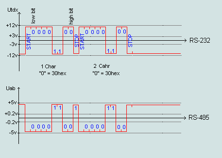 As seen from Figure 1 is a simple conversion of signal levels of voltage
Although the form of signals similar in the above mentioned standards, but the way of their formation and power signals are different.
Fig.2 Formation Signals RS-485 and RS-232
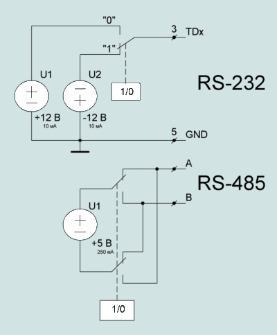 Converting signal levels and a new way of forming possible to solve several problems, which at the time were not taken into account when creating a standard RS-232.
Fig.3 Example of the converter.
 The situation when one will run more than one driver, RS-485 mode the transmitter leads to loss of data.
This situation is called "collision".
To no conflict arises in the channels of communication need to use higher protocols (OSI).
Such as MODBUS, DCON, DH485, etc.
Any programs that directly work with the RS-232 and solve the problem of collisions.
Typically, these protocols are called 485-mentioned protocols.
But in fact, the hardware basis for all these protocols is, of course, RS-232.
It provides hardware processing of information flow.
Software processing the data flow and problem solving to conflicts involved in higher level protocols (Modbus, and others) and software
Basic Principles of the upper-layer protocols (such as MODBUS
Let us briefly consider these protocols, although they are not relevant to the standard RS-485.
Usually, upper layer protocol includes a packet, staff or Frame-sharing organization.
That is, information is transferred logically completed parts.
Each frame must be marked, ie is denoted by its beginning and end of special characters.
Each frame contains the address of the device, command, data, checksum, which is required for multi-point exchange.
To avoid conflicts usually use scheme "leading" (master) - "Slave" (slave).
"Lead" has the right to switch your driver RS-485 mode of transmission, the other RS-485 drivers operating in receive mode and are called "slave".
In order to "slave" has begun to bring the data in the line of communication "leading" sends a special command that allows the instrument to the specified address the right to switch her driver in the transfer mode for some time.
When you send a resolution team "wingman", "leading" off its transmitter and waits for the answer "wingman" for a period of time, which is called "timeout".
If during the timeout response from a slave is not received, then the Master once again takes the line of communication.
In the role of "lead" is usually the software installed on your computer.
There are more complex organization of the packet protocol, which allows cyclically betray the role of "lead" from unit to unit.
Typically, such devices are called "leaders" or say that the devices transmit "cookie".
Possession of "marker" makes the device "master", but he should be sure to transfer it to another network device on a particular algorithm.
In general, the above-mentioned protocols are different for these algorithms.
We see that the upper protocols are batch organization and run on the software level, it can solve the problem with "collisions" of data and multi-point data exchange.
§7.Implementation transceiver (drivers) RS-485.
Many companies manufacture transceivers RS485.
They are referred to generally converters RS232 - RS485 converters, or RS232-RS485.
To realize these devices produced a special chip.
The role of these chips is to convert RS232C signal levels to the level of signals RS485 (TTL / CMOS) and back, as well as the provision of half-duplex mode.
Fig.4 Schematic diagram of RS232-RS485.
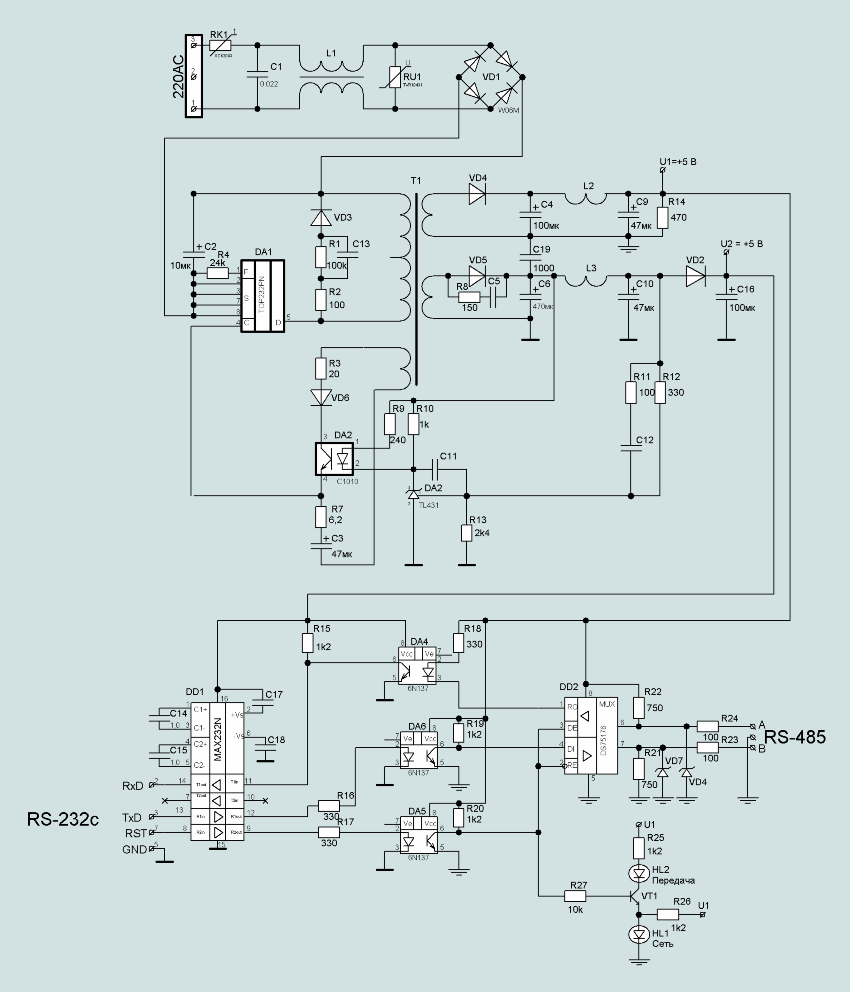
Figure 4 is a schematic drawing of the converter RS232-RS485. This converter has a separate signal to activate the data transfer. As a control signal used by the output signal of the COM port RST. If RST = 1 (+12 V) converter transmits data from TD (COM port) in the network RS485, if RST = 0 (-12), the data are taken from the network RS-485 to the input RD (COM port). The converter operates from an industrial AC voltage of 220 volts. The power supply converter is made by the pulse scheme based on the chip TOR232N (DA1). Power supply issues, two independent voltage +5 V. To receive and convert the polar signals RS232 (± 1912 V) single ended signals into TTL / CMOS level (+5 V) is used chip MAX232N (DD1). This circuit is interesting because it is powered from a unipolar +5 V and has a built-in voltage sources needed to work with polar signals of ± 12 V. For the correct operation of an integrated power voltage to the chip MAX232N connect the external capacitors C14, C15, C17, C18. In addition, IC has two levels of signal transducer RS-232C to TTL / CMOS in both directions.
Appointment Signals:Figure 5 Topology RS485 network
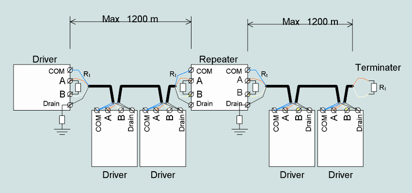 If the distance segment exceeds 1200 m or the number of drivers in the segment more than 32 pieces, you should use a repeater (repeater), to create the next segment.
Moreover, each segment of the network must be connected to the terminator.
Segment the network when it is considered an extreme cable between the device and repeater or between repeaters.
Standard RS-485 does not specify what type of symmetrical cable should be used, but de facto use cable twisted pair "with a wave resistance of 120 ohms.
Fig.6 Industrial Belden 3106A cable for RS485 networks
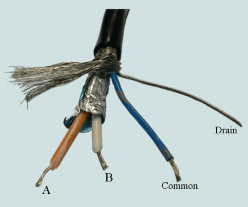 It is recommended to use industrial cable laying networks Belden3106A RS485.
This cable has an impedance of 120 ohms and a double screen twisted pair.
Belden3106A cable contains 4 wires.
Orange and white wire is a symmetrical shielded twisted pair.
Blue wire cable used to connect the zero-capacity power supply devices in the network and is called "common" (Common).
Wire without insulation is used for grounding braided cable, and is called the "drain" (Drain).
As part of the network drain wire grounded through the resistance of the chassis unit from one end of the segment to prevent stray currents flow through the sheath, with different potential land in remote locations
Usually the resistance terminators and protective grounding is inside the device.
You have to properly connect them with jumpers or switches.
In the technical documentation company instrument manufacturer to find a description of these connections.
For example, in Figure 7 shows the recommendation of the firm Allen Bradley on connecting cables to devices Belden3106A 1747-AIC (Link Coupler) used to connect to the network controller SLC DH-485
Fig.7 Wiring 1747-AIC (Allen Bradley)
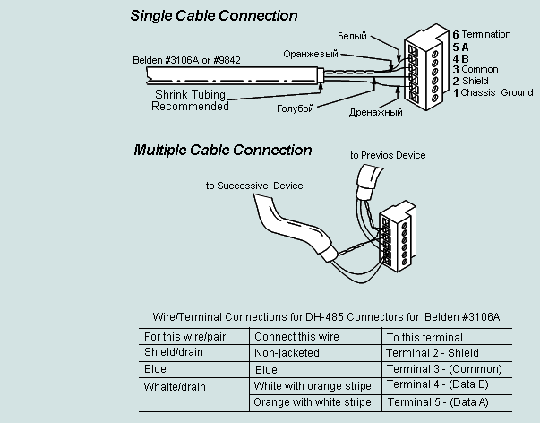 Fig.7 show the connection cable with intermediate devices segment.
For the first device in the network segment DH-485, you must install a jumper on 5-6 (which connects 120 ohm terminator, which is located inside the unit in 1747-AIC) and the jumper 1-2 (connects the drain conductor to the chassis through a device internal resistance).
For the last device in the network segment you want to install only jumper 5-6 (connect terminator)
When using other symmetrical cables, especially when you do not know their impedance, the value of terminators are selected empirically.
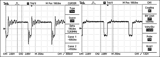
To do this, you must install the oscilloscope in the middle segment of the network.
By controlling the shape of rectangular pulses transmitted by one of the drivers can be concluded that adjustment of the resistance terminator.
Fig.8 Inconsistent network RS-485 (without the terminator) and its resultant waveform (left) compared with the signal received at a correctly terminated network (right)
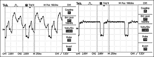
Fig.9 Terminator is installed in the middle segment of the network RS-485
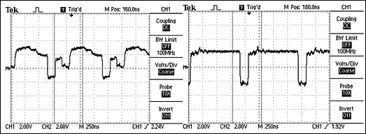
Fig.10 instrument connected long drop (3 m) to a segment of the network RS-485
More information about this can read the article Maxim's Application Note 373 2001
For the analysis of matching quality communication lines used test functions. Usually, this feature is built into a specific device or program. During the test the transmitter sends to the network specified sequence of characters, and the receiver at the other end of the line examines the correctness of the admission he knew the sequence of characters. The network is tested certain amount of time, after which the number of errors concludes as communication §9.Software for work in networks RS-485RS-485, was the main physical interface for industrial data networks. Protocols such as ModBus, ProfiBus DP, DCON, DH-485, work on the physical layer RS-485
Industrial data transmission protocols are often classified manufacturer.
For information on this or any other communication protocol has to be assembled bit by bit.
Specialists working with industrial networks need a program to read all the information transmitted in the information networks.
Basic Secrets of industrial protocols can be found only when a comprehensive analysis of data transmitted and received.
Program ComRead v.2.0 is designed to preserve and display the data and service signals transmitted in information networks, which operate on the standard RS-232, RS-485, Bell-202 and al
The program not only preserves all the information, but also creates a temporary scan data and service signals.
The program scans ComRead v.2.0 news channel without affecting its operation, ie running in listening mode of the physical environment of information transfer.
In addition, the program can operate in the translator data and service signals.
In this case it becomes a direct part of the information communication channel.
More details can be found with the program here .