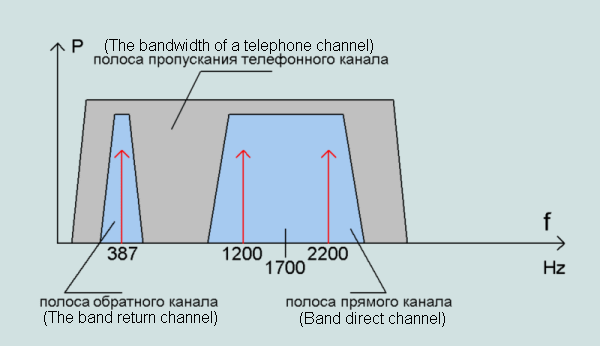
Fig.2 The spectrum of the signal in the mode in 1200 / 5 bps
direct channel: rate = 1200 bps, Mark = 1200 Hz, Space = 2200 Hz
Reverse channel: speed = 5 bps, Mark = 387 Hz

 Home
Back
Author: Electron18
www.softelectro.ru
2010
electron18@softelectro.ru
Bell 202 - Interface transfer serial binary data by the frequency manipulation. A first interface for transferring serial binary data. A corporation Bell System, for remote management and configuration of telecommunications equipment connection. The interface allows for an acoustic gap between the objects that share information. That is, information exchange can occur via handsets laid crosswise to each other. The unit and zero at this interface are encoded by different harmonics of the sound frequency range. Since the signals are in the range of audio frequencies, the bandwidth telephone channel is sufficient for the transfer of 1200 bits per second. The method of the frequency manipulation had come to replace the telegraph method of data transmission, which meant the character encoding by time intervals, such as Morse code.
Alexander Bell (Alexander Graham Bell) was a teacher in a school for deaf children in the city of Boston.
March 7, 1876 he received a patent for an invention your phone.
In 1877 Alexander Bell offered to buy his patent to the largest telegraph company Western Union Company.
President of the company proposed to consider this question the advice of experts in the field of telegraphy.
The experts gave the opinion that this invention is useless in the field of telecommunications and it is futile.
Alexander Bell decided independently to promote his invention.
Approximately 10 years later, the giant telecommunications Western Union Co., Was actually forced out phone business from the scope of telecommunication technologies.
Today you can see in many Russian cities windows that says Western Union, this company which is engaged in transferring money around the world, and once she was the international telecommunications giant.
Hence we can conclude: opinions of experts in innovative technologies are useless!
The company formed by Bell, which later became known as the Bell System, was the main generator of ideas in the theory and practice of transferring serial data.
Avoiding the use of temporary signals, such as "dot" - "dash", and the transition to a frequency modulation of the transmitted information was yet another innovative breakthrough.
The first modem company called Bell System Bell103 and Bell202.
Telephone networks with these modems served as the prototype of the modern world of information networks.
These modems can operate over existing then the telegraph and telephone. Interfaces, on which these modems were called on the name of modems.
The name of Alexander Bell deserved hit in the name of those interfaces.
Bell System Corporation has received from the U.S. government in 1877, a monopoly on telephone communications system.
Therefore, the development of this company, in particular interface Bell202, do not become serial data exchange standard, since they were patented method of exchanging data over the telephone networks of Bell System.
For this reason, the international standard ITU-T v.23 (analog Bell202) was forced to shift the frequencies used to transmit serial data.
In 1984, the monopoly Bell System was abolished and the monopoly was split into several major corporations: AT & T Inc., Cincinnati Bell Inc., Qwest Communications International Inc., Verizon Communications Inc., Alcatel-Lucent, Avaya Inc., LSI Corporation, Systimax Solutions, Telcordia Tachnologies Inc., Bell Canada Enterprises Inc., Nortel Networks Corporation, ITT, NEC, NTT.
Bell System (1876-1984ãã.)
Many sources indicate the company AT & T (but, it was part of the Bell System until 1984)
Publication: "Bell System Technical Reference, PUB 41212, Data Sets 202S and 202T Interface Specification, July 1976"
International standards have been forced to shift the frequency spectrum, as Bell202 was patented method of data transmission in telephone networks, Bell System.
ITU-T v.23 (1988 valid)
Publisher: TELECOMMUNICATION STANDARDIZATION SECTOR OF ITU
Title: 600/1200-BAUD MODEM STANDARDIZED FOR USE IN THE GENERAL SWITCHED TELEPHONE NETWORK
Oldest Received:
CCIT v.23 (1984 not valid)
CCIT v.23 (1980 not valid)
CCIT v.23 (1976 not valid)
GOST 20855-83 (1983)
Publisher: USSR. State Committee on Standards.
Title:Device signal conversion equipment for switched data and dial-tone frequency channel
-FSK (Frequency-Shift keying) frequency shift keying
often referred to as:
-AFSK (Audio Frequency-Shift keying) audio frequency shift keying
some sources indicate the modulation wrong:
-DPSK (Differential Phase Shift Keying) - different phase shift keying

When a binary sequence modulation technique FSK, frequency shift the transmitted signal with minimal phase change signal (Fig. 1). The amplitude of the signal modulation is not changed. Since uses only two harmonic frequencies, the spectrum of the transmitted signal is narrow (no more than 1 ... 2 kHz), which allows signals to pass freely through a dial-up lines of communication over long distances. Frequency modulation has good noise immunity, because it does not depend on the amplitude of the signal. Modem Bell202, call him on the current - driver ("driver"), may be active or not active. When the driver is active, he constantly sends a line connection signal with a frequency of 2200GTS, which allows other drivers to understand - that the line is busy and the driver is in transmit mode. If the input of the driver file binary sequence, then it starts to modulate its frequency shift (FSK). Units (Mark) modulated frequency 1200Gts, zero (Space) frequency 2200Gts. The driver stops to give a frequency signal, which becomes active when it is considered that it works in the mode of receiving data from the communication line
The interface Bell 202 has two communication channels, separated by frequencies. This enables both to transmit and receive data in both directions on the two wires. Direct channel of communication is fundamental. It is designed to transfer the basic flow of data at a speed of 1200 bps. The reverse channel is designed to confirm these data and can receive data at a rate of 5 bps or 150 bps.
In Bell202 has three modes:
1.asymmetrical duplex 1200 / 5 bps with a frequency division multiplexing

Fig.2 The spectrum of the signal in the mode in 1200 / 5 bps
direct channel: rate = 1200 bps, Mark = 1200 Hz, Space = 2200 Hz
Reverse channel: speed = 5 bps, Mark = 387 Hz
2.asymmetrical duplex 1200/150 bps with a frequency division multiplexing
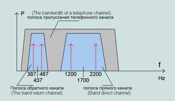
Fig.3 Spectrum of signal in the mode 1200/150
direct channel: rate = 1200 bps, Mark = 1200 Hz, Space = 2200 Hz
Reverse channel: speed = 150 bps, Mark = 387 Hz, Space = 487 Hz
3.half-duplex 1200 bps
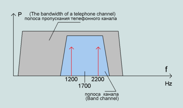
Fig.4 Spectrum of the signal in half duplex mode
Direct / reverse channel: speed = 1200 bps, Mark = 1200 Hz, Space = 2200 Hz
Bell202 interface is multipoint, in addition it can operate in half duplex mode.
Therefore, a situation may arise when one will run more than one driver Bell202 mode transmitter, which will lead to data loss.
This situation is called "conflict".
To no conflict arises in the channels of communication need to use higher protocols such as HART and others
Either the program that works directly with the modem Bell202 and solve the problem of collisions.
Usually such problems are solved assigning rights to the driver: 'slave "(Slave) or" leading "(Master).
Leading driver can independently include a data transfer mode in the line of communication, driven by the driver at the same time, there are in receive mode data.
To slave driver began to transmit data to the communication line must have permission from the moderator. This authorization is limited to the time, called to a timeout.
For the exchange of data and solve problems with collisions in the interface Bell202 provide service signals:
1. Callback tone, can detect the presence of a modem line connection.
Answer Tone (answering tone) - 900 Hz
2. Online software off the modem, is designed to turn off the modem.
Soft Turn-off Tone - 2025 Hz
As written above, the interface Bell202 intended to work with telephone and telegraph lines of communication.
The monopoly Bell System used it in their systems for remote control communications equipment and identify the caller numbers.
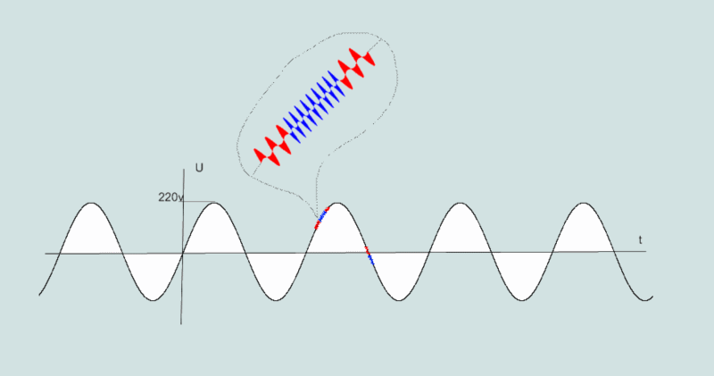
The bandwidth for the signal Bell202 small, so the interface can be used in various lines of communication:
Hardware implementation of transceivers Bell202 based on the frequency modulators and demodulators.
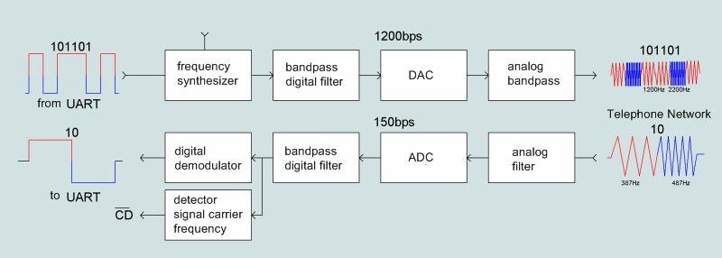
Figure 6 Functional diagram of a modem Bell202
Consider the functional scheme modem Bell202 shown in Figure 6.
In the direct channel, a binary sequence from the DTE (UART) on the RS232 comes to digital frequency synthesizer, which converts 1 and 0 in the frequency signals 1200 and 2200Gts. The duration of the modulated signal is then equal to the length of 0 or 1. Selection mode to specify settings of the synthesizer. Next, the digital frequency signal (rectangular shape) comes to a digital band-pass filter and digital-analog converter, in which the signal becomes a harmonic (sinusoidal) form. With cable analog filter band limits the output signal, eliminating him from the high harmonics (interference), formed by digital synthesis
In the reverse channel analog signal frequency 387/487Hz enters the bandpass filter, which provides an information signal from the communication line and submit it to the analog-digital converter. ADC digitizes the sinusoidal signal and a digital bandpass signal is fed to the demodulator, from which he comes in DTE (UART) Interface RS232C. In addition to the reverse channel to be the availability of carrier detector that allows to deliver the signal to begin the initialization data interchange between DTE (UART) and DCE (modem).
At present we produce integrated circuits that are wholly or partially perform the function of a modem with FSK-modulation.
Take, for example circuit RS232C-Bell202 converter ICs performed on AM7911.
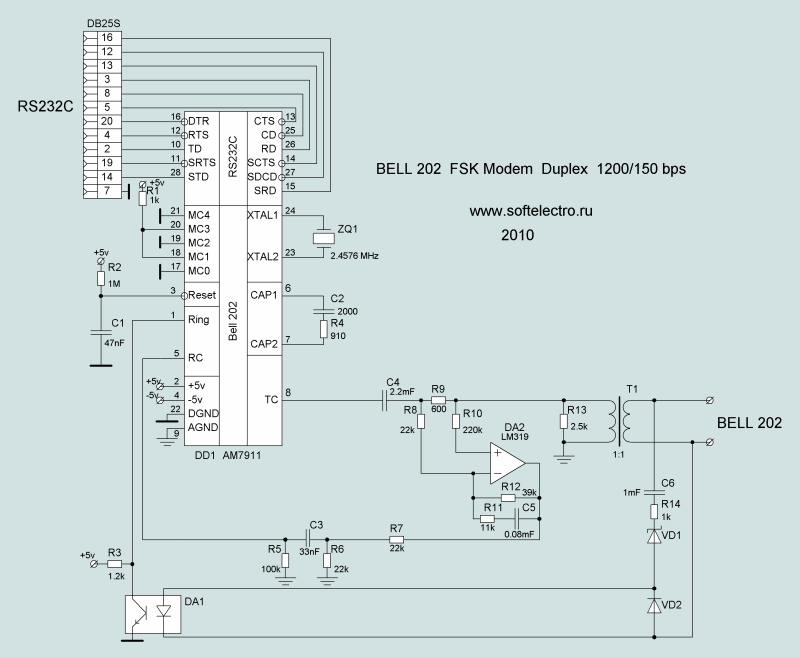
Fig.7 Diagram FSK-modem IC AM7911
AM7911 chip consists of a full-FSK-modem Bell202.
Circuit is powered from dual ± 5V source.
Figure 7 presented the standard scheme include ICs for work in full duplex 1200/150 bps.
Miniature transducer RS232c-Bell202 VIATOR firms MACTek power from the COM port of computer.
The modem operates in half duplex 1200 bps.
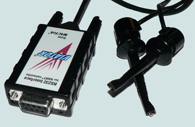
Fig.9 RS232 Interface for HART networks VIATOR from MACTek
Manual modem VIATOR Load Size: 46 kb
As noted in 3.6 interface Bell202 has a universal ability to work in many natural environments, which are used for data transmission.
Examples of this interface at present.
As indicated above interface created corporation Bell202 Bell System for remote configuration of telecommunications equipment for phone networks.
Bell System telephone networks owned by all the U.S., as had a monopoly on telephone service until 1984.
In most telephone networks around the world this interface is still used today.
For example, to define the number of the caller (ie, who is calling you), this function is called Caller_ID.
80-90s of the last century modems Bell202 actively used by hackers to break into a phone network, allowing them to make free calls to replace the caller's number and obtain illegal access to information.
In modern digital exchanges made protection from such actions.
Despite this world is a sufficient number of old telephone exchanges that are prone to "hacking" using the interface Bell202.
Currently, to exchange data via telephone networks Bell202 the modem is not used, it is replaced by a more sophisticated modems that provide high speed exchange, compression and error correction using cyclic coding.
For example, modems, v.92 c pulse code modulation.
Bell202 interface is the physical level to the international protocol HART. HART protocol has been developed by Fisher-Rosemount Systems for remote consultation and adjustment of its field devices. In the beginning, HART-protocol is used to configure devices through the connection of equipment HART-modem interface to the "current loop", on which the device passed its main parameter measurements in analog form. Today, HART protocol equip virtually all intelligent devices and equipment typically connects all devices equipment into a unified HART-network in which each device has its own address, by which it can be accessed using the device or program management. To work in the network requires a HART-HART-modem. HART-modem is a modem Bell202, and HART-Network is a network interface specification using Bell-202.
Example 1: Setting up a digital thermometer on the current loop 4-20mA.
There are digital thermometers measure temperature from 0 to 100 ° C, with HART interface.
The device transmits the temperature on the current loop 4mA = 0C ° C. .... 20mA = 100 ° C.
That is, the constant current in the current loop is directly proportional to the measured temperature.
The measured temperature is displayed on the voltmeter connected to the current loop through a resistance of 500 ohms.
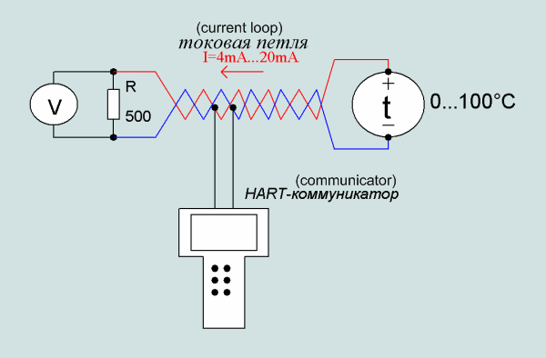
Fig.10 Adjustment of the instrument on the current loop.
To adjust the thermometer can be anywhere in the cable that carries a constant current of 4 to 20 mA HART-connected device.
HART-communicator, a digital device with a built-in modem Bell202, intended to set the TRC devices equipped with HART-interface.
Since the instrumentation may be out of reach, such as a radioactive zone, then this shows how useful the application of HART-Communicator to configure these devices.
In addition Bell202 does not require a separate line of communication, it can use existing lines of communication, such as current loop.
Example 2: Connecting devices in general HART-network.
In recent times more likely to use the connection instrumentation into a single HART-network that allows centralized configuration and management of devices.
When the need arises in the physical creation of HART-network, it usually consists of a wire network, with power supply and the load resistance equal to the output impedance of the modem.
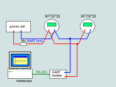
Fig. 11 Example of a HART-network.
Bell 202 interface is used in packet radio exchange protocol ITU-AX.25, on it by forming and processing of information packets.
Some of the most famous of Bell202 in radio:
1.Amateur Packet Communications (Amateur Packet Radio)
International network of amateur AX.25, working in a range of high frequencies, has in its structure transmitters, receivers, repeaters and gateways to connect to a network AX.25 with the global Internet network. To connect the computer modem transceiver uses Bell202 or specially designed for amateur radio BayCom modem.
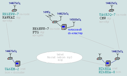
Fig.12 Example circuit AX.25 network in the North Caucasus. Taken from http://www.hamradio.cmw.ru
2. Automatic message position APRS (Automatic Position Reporting System)
This is a special version of the amateur packet radio.
With this protocol can obtain information on the location of the object or any of its measured physical parameters and with the help of technical devices to transmit them over long distances. It is used for positioning an object on the ground (such as GPS).
For example, apply for flight on balloons.
Space relay packet radio FSK (Bell202) 1200bps modulation is set to the Zarya module of the ISS, the frequency 145.825 MHz, callsign RSOISS-3. Radio amateurs around the world can use it to broadcast their packets via the ISS.
Because the modem Bell202 designed to work with UART via RS232, then any software that can work with the COM port of a PC can be used to work with this interface
For example, for viewing and recording on the hard disk of binary information transmitted in networks with FSK modulation 1200bps (Bell202) you can use the sniffer, such Comread v.2.

Figure 14 Record of binary information transmitted in the radio broadcast on the hard drive.