
 Home
Back
This page is translated from the original by using the Google translator.
ModemSE v.2.0
The terminal program for setting up and studying the work of modems
You can download the following files:
Program ModemSE v.2.1 Download Size: 1249 kb
The registration is free
§1 Description of the program.
The terminal program for simultaneous operation with two modems and software using the modem.
The main features of the program:
- Full-featured independent adjustment of two COM ports.
- Display input port in real time.
- Setting the output ports .
- Entering commands and data to control modems.
- Two terminals showing the exchange between the modem and COM port.
- Terminal and the translational mode.
Fig.1 The program window
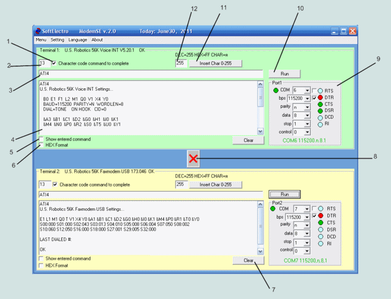
- On / Off adding a CR at the end of the command line
- Code a CR
- Command Line
- Terminal window to display the response from the modem
- On / Off Add content in terms of the command terminal window
- Displaying data in hexadecimal
- Clearing the contents of the terminal window
- Push Button Mode Terminal / Translator
- Element of COM port settings
- Button to send data to the command-line modem
- The button inserts a character in the command line, a digital ASCII code
- Digital code is inserted.
§2 Working with the program.
Configuring COM ports.
- Configure the ports by using the element 9.
- To the left of the window select the COM port is color indicator:
- -red: COM port is busy or does not exist.
- -green: COM port connected to the program and can work
- In other windows of the element 9 can select your COM port:
- -COM port number
- -exchange rate
- -scan mode (n-no, o-odd, e-parity, m-mark, s-space)
- -the number of bits per symbol
- -the length of the stop interval
- -mode of flow control (0-no, 1-software XON / XOF ,2-hardware RTS / CTS ,3-Programming hardware RTS / CTS / XON / XOF
- In Control 9 there arecolor indicators signal port:
- -Blue: the signal is not active
- -Red: output active
- -Green: the input signal is active
- The Control 9 switches are available that allow the on / off output signal COM port (DTR, RTS)
Terminal mode.
- In this mode, you can run two modems from a single computer.
AT commands are typed in the box 4. Pressing the button 10 to the command prompt, add code CR ( if On 1) command string to the modem.
The response received from the modem is displayed in the terminal window
- Modems can be connected to wire network and develop their cooperation on a single PC (which is quite handy).
Translational mode.
- This mode is ON / OFF button 8.
- In this mode, all data received on port2 will be transmitted to port1.
- The result of translation can be seen in a terminal window.
- This mode allows you to view any data exchange between software and a modem.
§3 Examples of use.
3.1 Terminal mode.
Using a telephone modem as a modem in BELL202 HART network
This program was written to address the issue:
Can I use dial-up modem as a modem in BELL202 HART network?
Available were three modem:
- - 3COM US-Robotics Voice Faxmodem Plus PCI(Model:#2976)
- - US-Robotics Faxmodem USB (Model: #5633)
- - VIATOR MACTek RS232(BELL202)
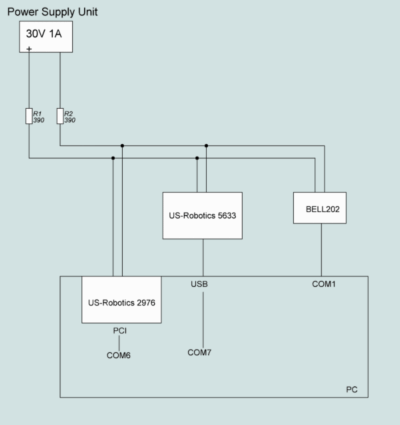
For the analysis of modems was collected two-wire network, as shown in Figure 2
Fig.2 Scheme of two-wire network.
- The theory of the experiment:
- 1. In the US-Robotics modem no modulation mode BELL202.
- 2.We will use the modulation ITU-T v.23, in which several signals are shifted MARK and SPACE.
In BELL202: MARK = 2200Hz SPACE = 1200HZ. In the ITU-T V.23: MARK = 2100Hz SPACE = 1300Hz.
The difference between BELL202 and V.23 is only 100Hz.
- 3.Modem Viator (BELL202) will observe the signals in the network.
- Run the program ModemSE v.2.0 and configure the modem:
- Expose the port settings: 1200, n, 8,1,0
- Successively introduce AT-commands for modems.
- ATL0 -low speaker volume (ìîäåì 2976-Îê, ìîäåì 5633-Ok)
- ATM2 -speakers are turned on always(modem2976-Îê, modem5633-Ok)
- ATB3 -option V.23(modem2976-Error, modem5633-Error)
- ATB0 -option v.22 (modem2976-Îê, modem5633-Error)
- ATF0 -full-duplex(modem2976-Îê, modem5633-Error)
- ATX0 -without ringing(modem2976-Îê, modem5633-Ok)
- ATN0 -disable auto speed detection(modem2976-Error, modem5633-Ok)
- AT&B1 -fixed port speed(modem2976-Îê, modem5633-Ok)
- AT&K0 -data compression allowed (modem2976-Ok, modem5633-Ok)
- AT&M0 -error control disabled (modem2976-Ok, modem5633-Ok)
- AT&A2 -indicate the type of modulation (modem2976-Îê, modem5633-Ok)
- AT&C0 -do not pay attention to the carrier (modem2976-Îê, modem5633-Ok)
- ATS0=0 -auto-reply to the call denied(modem2976-Îê, modem5633-Ok)
- ATS7=255 -do not expect the carrier(modem2976-Îê, modem5633-Ok)
- ATS10=255 -do not hang up the loss of carrier(modem2976-Îê, modem5633-Error)
- ATS27=16 -Modulation ITU-T V.23(modem2976-Îê, modem5633-Ok)
- As you can see all the settings are not perceived by these modems.
- Connect the modem:
- ATDT111 -dial a number on the modem2976
- ATA -answer the call to the modem5633
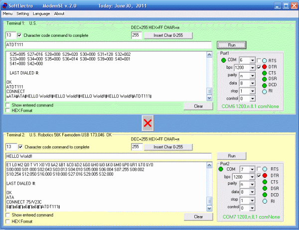
- After these actions have seen the connection of two modems with modulation v.23(Ðèñ.3)
- Full-duplex 75/1200bps
- modem2976 receive-1200 transmits-75bps
- modem5633 receive-75 transmits-1200bps
- Enter data into the modem5633: HELLO World!
- We see these data in the terminal windows 2976 modem and Viator (BELL202)
Fig.3 The program window after the connection and data transfer
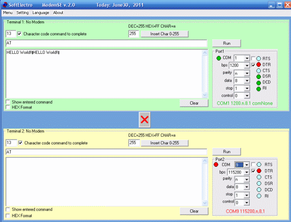
- Observations BELL202 carry through a second copy of the program ModemSe v.2.0, to which the modem is connected Viator
Fig.4 Observation Signal BELL202.
- Conclusion: Using a telephone modem may give the command to the HART network
Transferring data from the modem to modeme2976 Viator accepted with errors.
- The reason for the presence of carrier errors that creates modem5633.
- If you disable modem5633, the data from the modem Viater (BELL202) accepted modem2976 normal.
The conclusions of the work in the networks of telephone modems BELL202:
- 1.Possible to work with the modulation of ITU-T V.23 instead BELL202.
- 2.Telephone modems have a connection setup procedure, which is not a HART device users:
- -Therefore, you must decide how to dial-up modem will go to the ON-line mode with modulation V.23
- -In this experiment, we used a second modem for this purpose
- 3.You must configure the modem operation in half duplex mode:
- -This is due to the fact that full-duplex modem transmits continuously generates the carrier frequency in the network, disable it only at the time of sending the data.
- -This is evident in an experiment that can not pass duplex 75/1200 data to the network with a modem BELL202.
- 4.The main problem is the availability of a telephone modem carrier frequency, which is not used in the HART network.
- -First, in its absence there are difficulties in the transition to on-line mode.
- -Second, in the absence of the carrier after a while receiving modem exits on-line.
- 5.HART uses a network of permanently incorporated terminator, terminator telephone modem is connected only when you go online on-line.
- -Therefore it is necessary to coordinate the communication line when dealing with dial-up modem.
- 6.The modem uses the settings BELL202 exchange: "1200, o, 8,1", which does not support dial-up modem.
- -If you configure the COM port the modem mode "1200, o, 8,1", then it will transmit in the mode of "1200, o, 7,1".
- -Therefore, in our experiment we used mode: "1200, n, 8,1", which is a telephone modem.
3.2 Translational mode.
View modem commands software VentaFax v.5
This mode is used to view the AT-commands, which delivers software to use its modem.
To start the translational mode requires a null-modem cable connection diagram is shown in Figure 5.
ModemSE v.2.0 program with a null modem cable allows you to get inside the exchange to an external physical layer.
Fig.5 Example of translation mode.
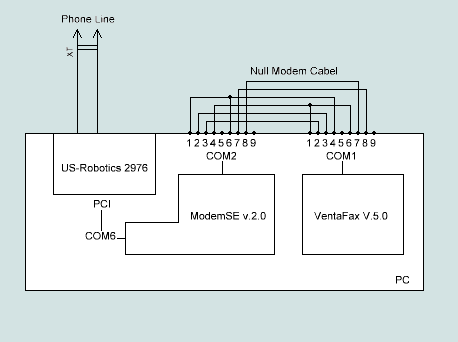
For the operation of the circuit is done as follows:
- 1.An internal PCI modem US-Robotics Voice 2976, which occupied the port COM6
- 2.In Windows XP Control Panel, phone modems, install another modem on an external port COM1.
- 3.In fact, this is not an external modem to this port, we connected via null-modem cable to COM2.
- 4.Run the program and we adjust ModemSE Port1 and port2 to COM6 on COM2.
- 5.Turn on the translation mode and run the program VentaFAX.
- 6.The program VentaFax choose US-Robotics modem installed on COM1.
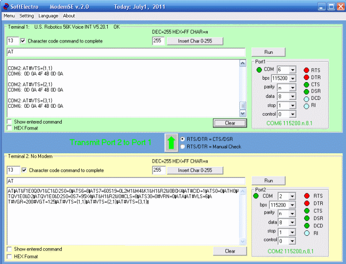
- 7.Further work with the program VentaFax and seeing through the exchange of ModemSE.
Fig.6 The program VentaFax picks up and dial 123.
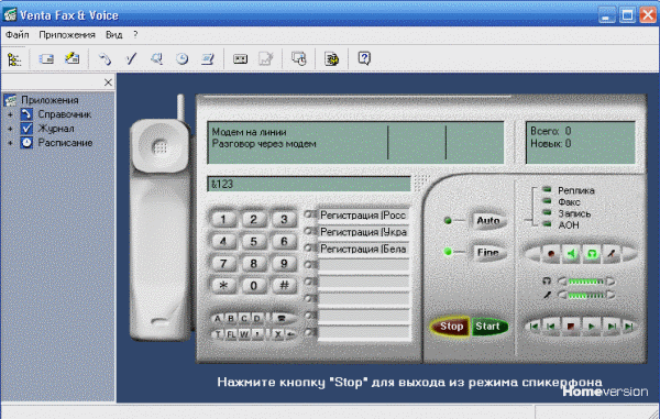
Fig.7 The program ModemSE observe a set of AT-commands executed.
That's it! Then think for yourself.
Back
Home


 Home
Back


