
 Home
Back
Home
Back
Author: Electron18
www.softelectro.ru
2009
electron18@softelectro.ru
This article is written solely for describing electroerosive method of processing metals. Description of the structure as a whole or any part thereof may not be a tool to create electroerosive machine. Electric circuit device and the machine breaks all rules of electrical and poses a real threat to your life, power and equipment. The author assumes no liability for damage caused to your health and property if you try to implement the design described here. Any part of this article can not be printed or transferred to anyone else without this warning. The author has made this machine for a specific task under the constraint of time and details. After solving this problem machine was dismantled, because it is absolutely not safe.
Write this machine made me the problem with the removal of a broken bits of high-sump rear axle of my car. Unscrewing the lid of the rear axle gear, I broke off the head bolt M8. In the absence of the extractor tried to use carbon in the form of a bat star, who scored a hole drilled in the remainder of the bolt. If you attempt to unscrew the remains of the bolt broke off a bit. Drill bits carbide drills chip failed. I had to think about how to do this without removing the bridge
The principle of spark erosion machining of metals is based on the evaporation of the metal spark discharge. If you have seen short-circuiting the capacitor on a metal plate, remember that in place of the discharge the remaining wells. Metal in this place is evaporated from a high temperature spark discharge. EDM machines more than 50 years are used in industry for processing high-strength alloys.
The main machine is a spark generator, and more precisely capacitor (energy storage). We need to accumulate electrical energy over a long period of time, and then throw all the accumulated energy in a very short period of time. By the same principle working lasers, the shorter the time will release the energy, the higher the current density in the spark channel, hence - will be higher temperature.
Fig.1. Schematic diagram of the spark generator.
Work spark generator:
With the diode bridge rectifies electric power 220.
Lamp H1 serves to limit short-circuit and protection diode of the bridge.
Instead, the lamp can use a different load. The greater the load (W), the faster the capacitor charge. But remember that the current must not exceed the capacity of the diode bridge and the connecting wires.
After the capacitors are charged H1 bulb goes out, and you can hold the electrode to the workpiece.
At the moment of contact of the electrode on the detail slip by a spark, causing capacitors to discharge and the lamp H1 illuminates.
After opening the electrode capacitors will be charged again.
Time charge capacitors in this circuit 0,5 .. 1,0 sec.
DC current in the circuit with a closed electrode is approximately 0.45 A, but at the time of discharge he reaches several thousand amperes.
Therefore, the wires from the capacitors to the electrodes should be thick (6 .. 10 mm2) and be sure to copper.
Bringing every second electrode to the details you will get a spark generator with a frequency generation in 1Hz
Workpiece should be conductive, ie it should be a metal or alloy of metals. The strength of alloys is not significant. The electrode should be copper or brass. Hole derived in detail, will repeat the shape of the electrode. If the electrode is triangular, then the hole in the details will be triangular. When working electrode is shortened due to evaporation of approximately the same speed with which to deepen the hole. The rate for the deepening of this scheme is about 0,025 mm per blow. That is, 40 beats depth of the holes will be about 1mm (for diameter hole 2 .. 3 mm). With an increase in the rate of deepening the hole diameter will decrease. After each impact, the hole will be covered from within the oxides of metals, and gradually the spark begins to fall, while not an end. Therefore, the second part of the machine should be a system of removal of oxides. For this to be lodged in the hole kerosene or oil. Removal of oxides is due to explosion of a drop of oil in the spark arc. The oil evaporates due to high temperature and reacts with oxygen, which is in the air, resulting in the hole occur click (explosion), which throws metal oxide surface. I used a spray with silicone lubricant. Suffice it after every third click splashing into the hole silicone grease and the spark will not disappear. Just be careful if you pour a lot of silicone it can catch fire. Electrode feeding should definitely fix the guide so that he beat all the time in one spot and moving parallel to the axis of the hole.
Parts for spark generator is not scarce, they can be bought in specialized shops or take the nearest dump. The capacitors you will find ejected in any TV or monitor, or the power supply from the computer. Ibid find and a diode bridge. Voltage as indicated on the capacitor must be at least 320 V. The capacitance can be any sum of all capacitors must be at least 1000 uF (all capacitors connected in parallel). The greater the capacity, the greater will strike. All this must be collected in a solid insulating housing. As I have said for the installation to use thick copper wire (6 .. 10mm2), which should go from the capacitors to the electrodes. The wires from the capacitors to the diode bridge and the lamp can be 0,5 mm2. The lamp set in a porcelain socket and firmly secure it on a stand, the lamp fell and shattered, it is desirable here to install circuit breaker for 2 .. 6 A. it can be used will include the scheme. For the electrodes have to do secure clamps. For the minus wire large crocodile or screw terminals. On the plus wire should do the time for a copper electrode and a tripod with a guide for the electrode.
Fig.2 Device Machine
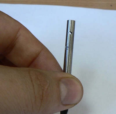
Building 6 machined Teflon. As a guide bushing 4 for an electrode used in the grounding pin 3-phase evrorozetki. He was drilled along the axis for the installation of the electrode into it and made two screw holes for fixing the electrode and wire. As the evaporation of the electrode it leaned forward, loosening the screw 2. The whole construction is mounted on a reliable tripod, which allows you to change the height. In the opening 6 is inserted tube with oil. Guide sleeve 4 serves as a syringe oil along the electrode.
Fig.3 Photo Machine
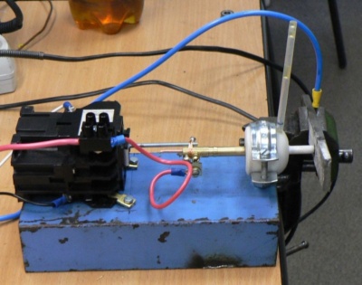
To drive the electrode was used domestic starter coil 220, a rod which has a course of 10 mm (it determines the maximum depth of holes). Starter winding is connected in parallel lamp H1, so while capacitors are charged (lamp lit) starter rod retracted. After charging the capacitor lamp goes out, as the current in the system ceases to flow and the stock is released. Releasing it relates to stock parts, there is a spark discharge, the lamp lights up and the H1 stem again retracted. The cycle repeats itself again, at a frequency of about 1Hz. If you need to increase the frequency, you will need to increase the power of the lamp H1. For details on the photos used files.
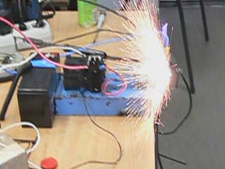
Fig.4 Photographs of drill hole performed by the machine.
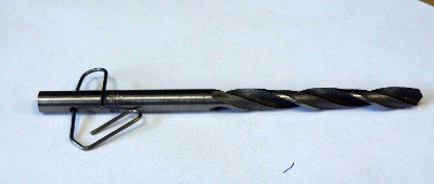
Therefore, I strongly do not recommend repeating this design.
And to develop and produce the design must Specialist, certified for such work.