 Home
Back
This page is translated from the original by using the Google translator.
Creating electrical circuits.
Identification of elements on the electrical circuits
Introduction.
Reading and drawing schematics is an integral part of the industrial engineer.
Standards for preparation of schematics and graphical display of elements were used extensively in the USSR and other countries.
The basis here was a unified system of design documentation ESKD.
In this article I want to present the basic principles and the art of drawing schematics.
At the same time draw your attention that this is not a description of standards, I would like to introduce the practice, which is used in the notation of the elements and produce good quality concepts
§1. Art drawing electric circuits.
Good strategy is not enough.
Create a good scheme long and boring, because you always need to remember, that you create a schema for a person, not simply describes a device for a certain standard.
Most schemes that have been created by ESKD, designers and engineers just ugly.
So I call the drafting of concept art.
Masterfully created by the scheme makes it much easier to work with the device.
Therefore, I advise to redraw the scheme for a device that you serve the time
Basis of concepts:
- Scheme needs a man and not a device;
- Should be a balance between detail and readability;
- Be graphically highlight the essence of the device and the importance of certain areas;
- Glance at the chart should show a clear path of its main functions
§2. De facto, the principal types of industrial electrical circuits.
We used two types of representations Electric circuits:
- big scheme of the device (in a huge sheet), with lists and other attributes ESKD.
- Album schemes A4 c many sheets (sometimes 100 or more pages)
The first type is characteristic of the Soviet period and the companies that work the old way.
Such a scheme is not suitable in all respects.
The main thing to find a large plane on which it can be decomposable.
After a while she'll completely useless, but take a copy of it is rather difficult.
Provide clear the device for such a scheme is not possible.
Surprising persistence of some large enterprises, which continue to produce such schemes.
The second type of more modern and actively applied, especially in imported equipment.
The disadvantage of these schemes is that the procedure simply flipping this scheme.
The majority simply draw separately each element of the scheme on a separate sheet, and the connection elements show links to pages and signals.
More advanced producers portrayed on separate sheets at least a chain of industrial safety equipment .
If you received a new machine, I advise you immediately draw the circuit block machine with all the elements, it will significantly reduce the time the withdrawal of equipment from his stupor.
Schemes, in which respected the balance of small and large (important and not important) is very small, the manufacturer does not bother it.
§3 The rules for electrical circuits.
Basic rules of making electrical circuits:
- Divide the device functions:
- Power
- Chain locks
- End input devices and signal transmission to the controler
- End output devices and signals to them from the controler
- Critical electronic device
- Exchange data with other equipment
- Well if we manage to depict these parts on separate sheets
- Traffic signals scheme ever! should be left to right. That is, the input terminal devices must be in the left part of the scheme, and the output terminal device in the right part of the scheme. (This applies to each individual item)
- Current supply in concept should flow from the top - down! That is the height of the scheme corresponds to a greater potential voltage. (This applies to each individual item)
- Do not overload the circuit connecting the wires, the main purpose to show the way the input information signals in their movement to the solver (or the solver to the executive end-devices). No major signals for this part preferably denote references.
- Can not display some elements of the scheme to improve readability, introducing less significant elements on separate sheets.
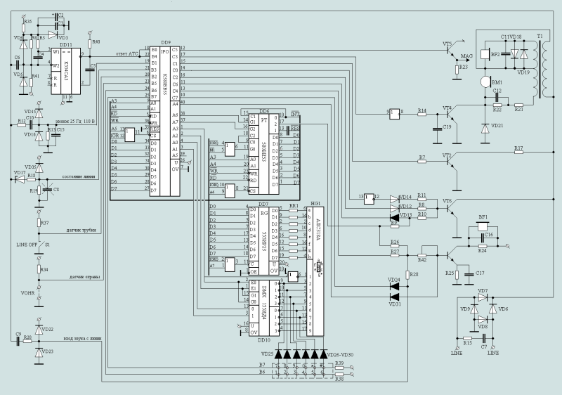
Fig.1 Schematic diagram of the AON (Input / Output Part)

Here, for example, part of the scheme AON, here are the input and output signals and the way they move.
The microprocessor portion of the device is not specifically shown, it is on a separate sheet.
And the signals from the microprocessor of the show from the bus.
Overall a tire of this circuit and microprocessor parts are connected, although it is somewhat contrary to ESKD, but once everything is clear, that where and how.
§4. Graphical representation of connections.
In electrical circuits there are differences between different industries in the image of the individual elements. There are traditions in the image of the circuit elements.
One can identify traditional schemes:
- Circuits, analog and digital devices
- Scheme of industrial equipment
- Circuit power supply and lighting
Further description is based on the circuits for analog and digital devices.
Plans electrical and industrial equipment, we consider separately.
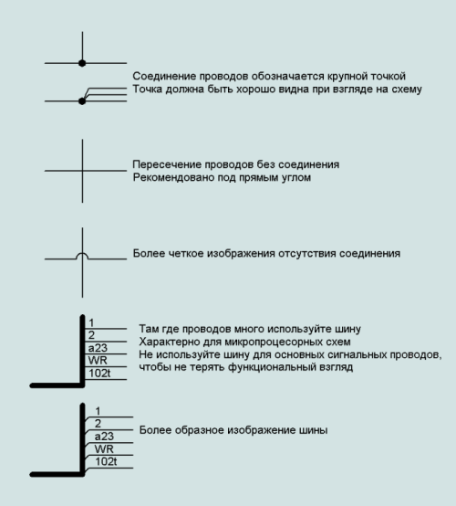
4.1 Connectors.

Each wire bus must have its own name. All wires in the bus with the same names are considered a single wire.
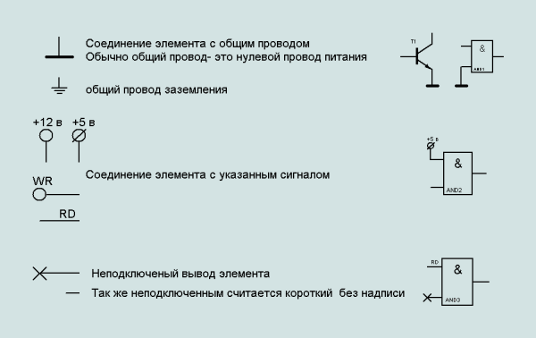
4.2 Connection with the common wires.
All signals from the same images and words are connected.
Use these signs to facilitate the graphic image.
Moreover, for the power wires obey the rule: "current must flow from top-down"

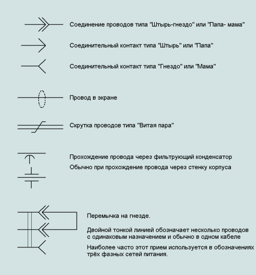
4.3 Special marking compounds.
Special designations are used to specify properties of compounds.

§5. Identification of elements on electrical circuits.
Each element of the electrical circuit is denoted by an alphanumeric code.
There are many options for signs, here I quote the most common, which corresponds to GOST 2.710-81 (ST SEV 6300-88)
The rules refer to elements in the scheme:
- Designation element is applied above his image, although the designation is permissible to inflict the right of the element, or even where there is free space;
- Value element is applied below the picture element, or permissible under the name of the element.
- Identical elements signed by the same letter code, but each element has its own individual serial number
- Numbering identical elements in the scheme is in order from top to bottom and from left to right.

Usually full face value element specifies a list attached to the concept, but admits GOST 2.702-75 simplified application value element to an electrical circuit:
for resistors:
- From 0 up to 999 Ohm — without the instruction of units of measure,
- From 1*10^3 up to 999*10^3 Ohm — in kilohm with a designation a lower case letter to,
- From 1*10^6 up to 999*10^6 Ohm — in megaohms with a designation a capital letter of M,
- From above 1*10^9 Ohm — in Gigo Ohm with a designation capital letter G;
for capacitors
- from 0 to 9999 * 10 ^ -12 F - in picofarads without specifying the units
- From 1*10 ^-8 up to 9999*10 ^-6 F — in microfarad with a designation lower case letters mk.
But the prevailing practice of marking values of capacitors is as follows:
- denomination without a comma - pF (100 - 100 pF)
- denomination with a comma - mf (0,1 - 0,1 mf)
In some schemes, it is used for the resistors (but this is not correct)
To indicate an element type are encoded in Latin capitals
The first letter in the mandatory and defines the element type, the second letter breaks the type of items for a subset.
A -The device (the general designation)
B- Converters of not electric sizes in electric (except for generators and power supplies) or on the contrary analog either multidigit converters or gauges for the instruction or measurements
- BA-Speaker
- BB-magnetostrictive element
- BC-selsyn sensor
- BD-radiation detectors
- BE-selsyn receiver
- BF-Phone (capsule)
- BK-Heat Sensor
- BL-Photocell
- BM-Microphone
- BP-pressure sensor
- BQ-piezo
- BR-speed sensor (tachogenerator)
- BS-Pickup
- BV-speed sensor
-Integrated circuits, micro-
- DA-scheme of the integrated analog
- DD-Integrated circuits, digital, logic element
- DS-Storage Information
- DT-delay device
E-elements of different
- EK-heating element
- EL-lamp lighting
- ET-squib
F-arresters, fuses, protective devices
- FA-discrete element of protection by the current instantaneous
- FP-discrete element of protection for the current inertia of
- FU-fuse fuse
- FV-discrete element protection voltage, discharger
G-generators, power
- GB-Battery
H-indicator devices and signal
- HA-device alarm
- HG-digit LED
- HL-light signaling device
K-relays, contactors, starters
- KA-switch a current
- KH-pointing Relays
- KK-electrothermal relays
- KM-contactor, magnetic starter
- KT-Relays
- KV-voltage relay
L-inductors, chokes
- LL-choke fluorescent lighting
-devices, measuring equipment. Note. The combination of PE use is not permitted
- PA-Ammeter
- PC-counter pulses
- PF-Cymometer
- PI-counter active energy
- PK-reactive energy counter
- PR-Ohmmeter
- PS-recording device
- PT-clock, measuring the duration of
- PV-Voltmeter
- PW-Wattmeter
Q-switches and circuit breakers to power circuits (power supply, power equipment, etc.)
- QF-circuit breakers
- QK-shorting
- QS-Disconnector
R-Resistors
- RK-Thermistor
- RP-Potentiometer
- RS-shunt measuring
- RU-Varistor
S-switching devices in control circuits, alarm and measurement. Note. Designation SF used for devices that do not have contacts of power circuits
- SA-switch or switch
- SB-button switch
- SF-circuit breakers
- SL-switches that trigger the level
- SP-switches, triggered by pressure
- SQ-switches that trigger the position (track)
- SR-switches, triggered by the rotation frequency
- SK-switches, triggered by temperature
T-Transformers, auto
- TA-CT
- TS-Electromagnetic Stabilizer
- TV-voltage transformer
U-device communication. Converters of electrical quantities in electrical
- UB-Modulator
- UR-Demodulator
- UI-discriminator
- UZ-frequency converter, inverter, frequency generator, a rectifier
V--electrovacuum devices and semiconductor
- VD-diode, diode
- VL-unit voltage regulator
- VT-Transistor
- VS-Thyristor
W-lines and microwave components. Antennas
- WE-coupler
- WK-shorting
- WS-Valve
- WT-transformer, heterogeneity, phase shifter
- WU-Att
- WA-Antenna
X-Links Contact
LI> XA-current collector, contact sliding
- XS-nest
- XT-Connection demountable
- XW-high-frequency connector
Y-mechanical devices with an electromagnetic drive
- YA-electromagnet
- YB-brake with electromagnetic drive
- YC-coupling with an electromagnetic drive
- YH-Electromagnetic chuck or plate
Z-terminal device filters. Terminators
- ZL-limiter
- ZQ-Quartz Filter
Author: Electron18
www.softelectro.ru
2009
electron18@softelectro.ru
Back
Home


 Home
Back


